
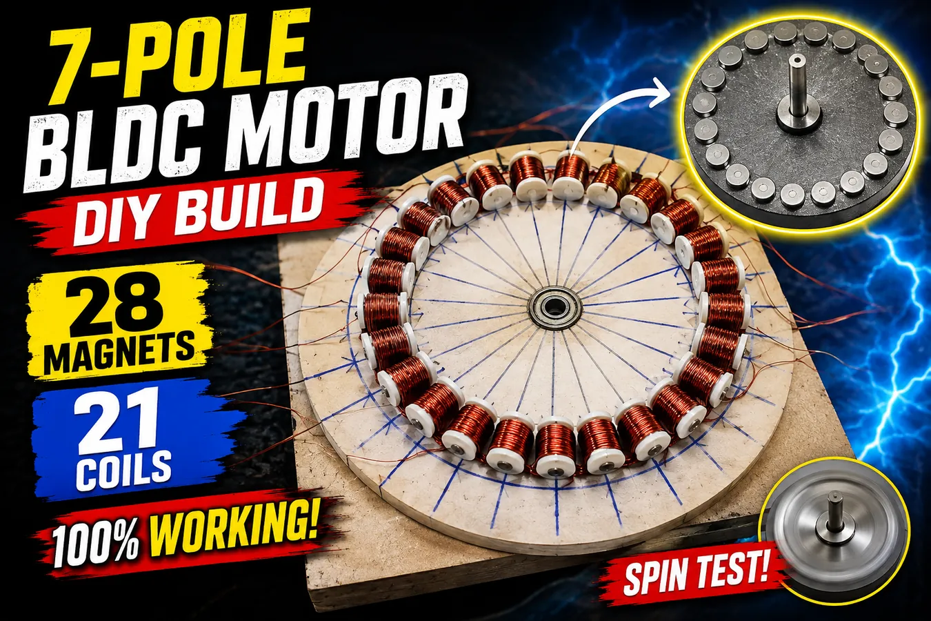
DIY 7 Pole BLDC Motor: 28 Magnets and 21 Coils
A DIY 7 pole BLDC motor is an interesting hands-on project for anyone who wants to understand how brushless DC motors work, how permanent magnets interact with copper coils, and how a three-phase winding system produces continuous rotation. In this build, we are creating a custom BLDC motor using 28 permanent magnets and 21 copper coils, with the coils divided into three phases. The project begins with an 8-inch wooden plate that serves as the foundation for the stator winding arrangement. Since the position of every coil affects the magnetic interaction inside the motor, accurate spacing is one of the most important parts of the construction process. We use a compass and carefully divide the circular plate into 21 equally spaced positions, creating a clear guide for installing the 21 bobbins. Each bobbin will eventually hold a copper-wire coil, and maintaining equal spacing helps keep the winding arrangement organized and symmetrical. This type of DIY electric motor project is particularly useful for learning the fundamentals behind BLDC motor design, three-phase motors, permanent magnet motors, coil winding, electromagnetic rotation, and motor controllers without relying only on theoretical diagrams. Unlike a traditional brushed DC motor, a brushless motor does not use mechanical brushes and a commutator to switch current. Instead, electronic switching through a suitable controller energizes the motor phases in the required sequence, creating a rotating magnetic field that interacts with the permanent magnets mounted on the rotor. In our seven-pole demonstration, the rotor contains 28 magnets while the stationary winding section contains 21 coils, giving the project a distinctive magnetic and electrical arrangement to experiment with. As we build the motor step by step, attention to measurements, coil placement, winding consistency, electrical connections, rotor alignment, and mechanical clearance becomes extremely important. Even a small error in spacing or winding can affect how smoothly the finished motor operates. The goal of this project is not simply to make a motor spin, but to demonstrate in a practical way how copper wire, electromagnetic fields, permanent magnets, a rotor, a stator, and a BLDC controller can work together to produce rotary motion. This makes the project valuable for electronics enthusiasts, engineering students, makers, hobbyists, and anyone searching for practical information about how to build a BLDC motor at home. In the following sections, we will go deeper into the construction process, including preparing the 21-coil stator, installing and winding the bobbins, creating the three-phase winding arrangement, connecting the phases, assembling the 28-magnet rotor, and finally testing the completed motor. The emphasis throughout the build is on understanding the purpose of each stage rather than simply following a sequence of steps. By the end, you will have a much clearer picture of how a custom 7-pole DIY BLDC motor can be constructed and why accurate coil placement and magnetic alignment are essential for successful operation.
Preparing the 21 Coil Stator Plate
The foundation of our DIY BLDC motor is the stator plate, and preparing this part accurately is essential because it determines the position of all 21 coils. For this project, we use an approximately 8-inch wooden circular plate as the base for the coil arrangement, although the exact dimensions can be adjusted depending on the intended motor design. The first job is to establish the center of the plate and create a consistent circular layout for the 21 bobbins. Using a compass or suitable measuring method, divide the circumference into 21 equally spaced positions and draw a small reference line at each location. Equal spacing is extremely important because the coils need to maintain a regular relationship with the rotating magnetic field produced by the rotor. If some bobbins are noticeably closer together or farther apart, the magnetic behavior may become uneven and the finished motor may experience vibration, inconsistent torque, noise, or difficulty starting. Once the 21 reference points have been marked, carefully place one bobbin at each position and check its orientation before applying adhesive. Every bobbin should sit securely and follow the same overall alignment so that the copper windings will have a consistent relationship with the rotor magnets. After positioning all 21 bobbins, use an appropriate adhesive to secure them firmly to the wooden plate. Apply enough glue to prevent movement, but avoid excessive adhesive that could interfere with the winding area or make future adjustments difficult. Work around the plate systematically rather than installing the bobbins randomly, because a consistent installation sequence makes it easier to identify missing or incorrectly positioned components. Once all 21 bobbins are attached, allow the adhesive to cure completely according to the manufacturer's instructions. Do not rush this stage; a bobbin that moves during winding can change the coil position and potentially damage the copper wire. After the glue has dried, inspect the entire stator plate from several angles and verify that every bobbin is firmly attached, evenly distributed, and aligned with its reference mark. This simple inspection can save considerable time later because correcting a misplaced bobbin after the coils have been wound is much more difficult. The 21-coil stator is the stationary part of our motor and will eventually generate the electromagnetic fields that interact with the permanent magnets on the rotor. This is one of the most important concepts to understand when learning how a BLDC motor works: the rotor carries the permanent magnets and rotates, while the stator contains the energized windings that create the changing magnetic field. In this DIY project, the wooden plate is primarily being used as a practical construction base for demonstrating the concept, so the finished assembly should always be evaluated for mechanical strength, heat resistance, electrical insulation, and safe operating conditions before attempting extended operation. With the 21 bobbins evenly positioned and securely fixed, the stator foundation is now ready for the most detailed part of the project—the copper-wire winding process, where each bobbin will receive a carefully controlled number of turns to create the three-phase winding system.
Winding 21 Coils with 0.455 mm Copper Wire
With all 21 bobbins securely installed on the stator plate, we can begin one of the most important stages of this DIY 7-pole BLDC motor project: winding the copper coils. For this build, the winding uses approximately 0.455 mm copper wire, and each coil is wound with 80 turns. Keeping the number of turns consistent is critical because differences between coils can change their electrical resistance, inductance, and magnetic behavior, potentially causing an unbalanced three-phase system. Start with the first bobbin and carefully feed the copper wire around the winding area, maintaining steady tension as each turn is placed beside the previous one. The objective is to create a neat and compact winding rather than allowing the wire to overlap randomly. A consistent winding pattern makes the finished stator easier to inspect and helps ensure that each coil has a similar electrical and physical configuration. Count every turn carefully until you reach exactly 80 turns, then leave an appropriate length of wire at the end for making the electrical connection later. The wire ends should be clearly identified and protected from accidental damage while the remaining coils are being wound. After completing the first coil, follow the predetermined winding sequence around the plate. In the arrangement demonstrated in this project, two bobbins are left between successive wound positions before starting the next coil, creating the required spacing for the first phase. Continue this pattern until seven coils have been completed for the first phase. The winding direction should remain consistent from coil to coil unless the specific motor design calls for a different connection arrangement. Consistency is especially important in a multi-phase motor because reversing a coil unintentionally can change the magnetic polarity produced by that coil and interfere with the intended rotating magnetic field. After finishing the first group of seven coils, inspect every winding and confirm that each coil contains the intended 80 turns. Look for damaged insulation, crossed wire, loose turns, or sections where the copper wire has been forced tightly against an edge. The same winding procedure is then repeated for the second phase, again using the 0.455 mm wire and 80 turns per coil. Once seven coils have been completed for the second phase, repeat the process for the third phase until all 21 coils have been wound. The result is a three-phase stator consisting of seven coils per phase, with every coil following the same basic winding specification. This stage demonstrates why BLDC motor coil winding requires patience and precision. The wire may look simple, but the electrical characteristics of the finished motor depend heavily on how consistently the coils are produced and connected. It is also useful to keep the wire ends organized and label them as you work, because identifying the beginning and end of each phase becomes much easier before the stator becomes crowded with wires. Remember that the exact wire size, number of turns, coil dimensions, winding sequence, magnet strength, air gap, controller characteristics, and operating voltage all influence the performance of a custom motor, so the values used in this demonstration should not automatically be treated as a universal BLDC motor design formula. After completing all 21 coils, perform a thorough visual and electrical inspection before connecting any power source. At this point, the heart of our custom three-phase BLDC motor winding is complete, and we are ready to move on to connecting the individual phases into a configuration that can be controlled electronically.
Frequently Asked Questions About DIY BLDC Motors
A BLDC motor, or Brushless DC motor, is an electric motor that uses permanent magnets and electronically controlled coils to produce rotation. Unlike brushed DC motors, BLDC motors do not use mechanical brushes and a commutator. Instead, a controller electronically switches the motor phases to create a rotating magnetic field.
A DIY BLDC motor works by creating an electromagnetic interaction between stator coils and permanent magnets mounted on a rotor. When a suitable BLDC controller energizes the three-phase coils in sequence, the resulting magnetic field interacts with the rotor magnets and produces rotational torque.
This particular DIY BLDC motor project uses 28 permanent magnets mounted on the rotor. The magnets are arranged around the rotor so they can interact with the electromagnetic fields produced by the 21 stator coils.
The motor uses 21 coils arranged around the stator. These 21 coils are divided into three electrical phases, with seven coils assigned to each phase in the demonstrated winding arrangement.
The demonstrated motor uses approximately 0.455 mm enamel-coated copper wire for the stator windings. Copper wire size affects resistance, current capacity, heating, and the electrical characteristics of the finished motor.
Each coil in this particular project is wound with 80 turns of 0.455 mm copper wire. Maintaining the same number of turns on each coil helps create a more consistent winding arrangement between the different phases.
Even coil spacing helps maintain the intended electromagnetic relationship between the stator and rotor. Accurate positioning can contribute to smoother magnetic interaction, while poor spacing may result in uneven operation, vibration, noise, or reduced motor performance.
Three-phase winding is commonly used in BLDC motors because it allows the controller to create a rotating magnetic field by switching the phases in sequence. This rotating field interacts with the permanent magnets on the rotor to produce continuous rotational movement.
The BLDC controller electronically controls current through the motor phases. By switching the phases at appropriate times, the controller creates the changing magnetic field required to keep the permanent-magnet rotor turning.
Yes, a BLDC motor can be constructed as an educational DIY project using suitable materials, tools, magnets, copper wire, a rotor, stator, and compatible controller. However, accurate construction and electrical and mechanical safety are important, especially when testing a homemade motor.
A brushed DC motor uses mechanical brushes and a commutator to switch current between its windings. A BLDC motor replaces this mechanical switching system with electronic commutation controlled by an electronic controller, which can reduce brush-related wear and allow different motor designs.
Permanent magnets provide the rotor's magnetic field without requiring electrical power through rotor windings. When the stator coils are energized by the controller, their magnetic fields interact with the permanent magnets and generate the torque needed for rotation.
Incorrect winding direction, coil polarity, spacing, or phase connections can prevent a BLDC motor from starting correctly or can cause rough rotation, vibration, excessive current, or heating. Every coil and phase should therefore be checked carefully before applying power.
The number of turns affects important electrical characteristics of a motor, including its resistance, inductance, magnetic field strength, and back-EMF characteristics. Increasing or decreasing the number of turns can therefore change the motor's speed and torque characteristics.
The stator is the stationary part of the motor that contains the electromagnetic windings. In this DIY project, the 21 copper-wire coils are mounted on the stationary plate and generate the magnetic fields that interact with the rotor.
The rotor is the rotating part of the motor. In this project, the rotor contains 28 permanent magnets that interact with the magnetic field generated by the 21 stator coils.
The air gap is the space between the rotating rotor and stationary stator. A properly aligned and consistent air gap helps maintain predictable magnetic coupling while preventing the rotor from physically contacting the coils or stator during operation.
Vibration can result from several factors, including uneven rotor balance, incorrect magnet placement, inconsistent coil positioning, phase connection problems, bearing misalignment, or an uneven air gap. Careful mechanical and electrical inspection can help identify the cause.
Building a small BLDC motor can be an educational project, but electrical and mechanical precautions are necessary. Strong magnets, rotating components, electrical current, and heat can create hazards. Use appropriate protective equipment, secure the motor properly, insulate electrical connections, and disconnect power before making adjustments.
Yes, experimental BLDC motor designs can be modified by changing factors such as coil dimensions, wire diameter, number of turns, magnet size, rotor geometry, air gap, and controller characteristics. However, changing one component can affect the electrical and mechanical behavior of the entire motor, so modifications should be tested carefully.
This project provides practical experience with electromagnetic fields, permanent magnets, copper-wire winding, three-phase motor connections, electronic commutation, rotor and stator design, and basic motor testing. It is a useful hands-on way to understand the fundamental principles behind brushless electric motors.
Discussion
No comments yet. Be the first to join the conversation!