
Introduction
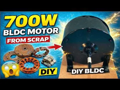
Building a 700-watt Brushless DC (BLDC) motor from recycled and scrap materials is an exciting project that combines engineering, creativity, and sustainability. Instead of purchasing expensive new components, many of the essential parts—such as the stator core, permanent magnets, bearings, shaft, and metal housing—can often be recovered from discarded electric motors, hoverboards, treadmills, washing machines, power tools, and other electronic equipment. By carefully selecting and restoring these components, hobbyists and makers can construct a reliable BLDC motor capable of delivering impressive performance while significantly reducing project costs.
BLDC motors are widely recognized for their high efficiency, long service life, quiet operation, and low maintenance requirements. Unlike traditional brushed motors, they eliminate mechanical brushes and commutators, reducing friction, wear, and energy losses. These advantages make BLDC motors the preferred choice for electric bicycles, drones, industrial automation, electric vehicles, cooling fans, robotics, CNC machines, and countless other modern applications where efficiency and reliability are essential.
Reusing scrap materials also helps minimize electronic waste, conserves valuable resources, and promotes environmentally responsible manufacturing practices. Salvaging usable components gives old equipment a second life while providing valuable hands-on experience in motor design and electrical engineering.
In this guide, you will learn how a 700-watt BLDC motor works, how to identify suitable scrap components, design the motor, wind the stator coils, assemble the rotor, connect the electronics, test performance, troubleshoot common issues, and perform routine maintenance to keep the motor operating safely and efficiently.
Understanding BLDC Motor Design and Collecting Scrap Components
A Brushless DC (BLDC) motor operates by converting electrical energy into rotational mechanical motion without using traditional carbon brushes or a mechanical commutator. Instead, permanent magnets mounted on the rotor interact with a rotating magnetic field generated by the stator windings. An Electronic Speed Controller (ESC) energizes the stator coils in a precise sequence, a process known as electronic commutation. As the magnetic field continuously changes, the rotor magnets are attracted and repelled in succession, causing the shaft to rotate smoothly. Because there are no brushes rubbing against a commutator, friction and mechanical wear are greatly reduced, resulting in higher efficiency, quieter operation, less maintenance, and longer service life. BLDC motors also generate less heat and can operate at higher speeds with improved torque control, making them an excellent choice for electric vehicles, industrial automation, robotics, drones, cooling fans, and many DIY engineering projects.
A typical 700-watt BLDC motor consists of several essential components that work together to produce reliable performance. The stator is the stationary section containing laminated steel cores and copper windings that generate the rotating magnetic field. The trong>rotor carries permanent magnets, usually high-strength neodymium magnets, which respond to the changing magnetic field created by the stator. A precision steel shaft transfers the motor's rotational power to the driven equipment, while bearings support the shaft and minimize friction for smooth operation. The motor housing protects the internal components, maintains proper alignment, and helps dissipate heat. High-quality enamel-coated copper wire is used for the stator windings because of its excellent electrical conductivity and insulation. Many BLDC motors also include Hall-effect sensors, which detect rotor position and improve low-speed starting performance, although sensorless designs are also common. Finally, an Electronic Speed Controller (ESC) manages the switching sequence of the three motor phases, regulates speed, controls acceleration, and provides protection against overcurrent, overheating, and voltage fluctuations.
One of the greatest advantages of a DIY BLDC motor project is that many of these components can be obtained from discarded electrical equipment. Old washing machines often contain robust stator laminations and quality bearings suitable for motor construction. Treadmill motors provide durable shafts, housings, and mechanical hardware that can be adapted for custom designs. Broken hoverboards and electric bicycle hub motors are excellent sources of high-grade neodymium magnets, stators, and precision-machined parts specifically designed for brushless motors. Smaller devices such as laser printers, hard disk drives, and computer cooling fans contain useful bearings, magnets, shafts, and electronic components that can be repurposed. Worn-out power tools, cordless drills, angle grinders, and garden equipment may also provide reusable mechanical parts and fasteners. Electronic recycling centers, repair workshops, scrapyards, surplus stores, and discarded household appliances are all valuable places to search for affordable components. Careful selection of reusable materials can significantly reduce construction costs while keeping functional parts out of landfills.
Before incorporating salvaged components into a new motor, each part should be carefully inspected and restored. Bearings should rotate freely without grinding noises, excessive play, or signs of overheating. Any worn or damaged bearings should be replaced to ensure smooth and reliable operation. Permanent magnets should be checked for chips, cracks, weakened magnetic strength, or loose mounting surfaces. The shaft should be perfectly straight and free from bends, corrosion, or excessive wear, as even slight misalignment can create vibration at high rotational speeds. Copper windings salvaged from existing motors should be examined for damaged insulation, burn marks, or broken conductors that could cause electrical faults. Steel laminations and metal housings should be cleaned thoroughly to remove rust, grease, paint, dust, and debris using suitable cleaning methods. Electrical continuity can be verified with a digital multimeter, while insulation resistance testing helps confirm that the windings remain electrically isolated from the motor frame. Performing these inspections before assembly increases reliability, improves efficiency, and reduces the likelihood of costly failures during testing.
Building a high-quality 700-watt BLDC motor also requires the proper tools and materials. Essential materials include enamel-coated copper wire of the appropriate gauge, laminated stator cores, neodymium permanent magnets, a precision steel shaft, high-quality bearings, epoxy adhesive, insulating varnish, slot insulation paper, heat-shrink tubing, electrical connectors, mounting bolts, and a compatible Electronic Speed Controller. A reliable digital multimeter is necessary for measuring voltage, resistance, and continuity throughout the construction process. Digital calipers and a micrometer help verify accurate dimensions, while soldering equipment is required for making secure electrical connections. Bearing pullers and installation tools simplify bearing replacement without causing damage. A drill press or small milling machine assists with accurately machining mounting holes and brackets, while a rotor balancing stand helps minimize vibration during high-speed operation. Additional useful equipment includes wire strippers, crimping tools, hex keys, torque wrenches, files, sandpaper, clamps, and precision measuring tools. Finally, always wear appropriate personal protective equipment, including safety glasses, insulated gloves, hearing protection when using power tools, and a dust mask when grinding or cleaning metal parts, to ensure a safe and professional workshop environment.
Designing the 700-Watt BLDC Motor
The first step in designing a 700-watt BLDC motor is defining the target performance specifications based on its intended application. A motor designed for an electric bicycle may prioritize high starting torque and moderate speed, while one intended for a water pump or workshop machinery may require continuous operation at a fixed RPM. Begin by selecting the desired power output of approximately 700 watts and determine the operating voltage, such as 24V, 36V, or 48V DC, depending on the available battery or power supply. Once the voltage is chosen, calculate the expected current using the power equation (Power = Voltage × Current), allowing additional capacity for startup and peak loads. Next, establish the target rotational speed (RPM) and torque requirements, since these directly influence the winding design, magnet configuration, and controller selection. Higher RPM generally produces greater speed, while higher torque is achieved through increased magnetic flux and optimized winding geometry. Cooling requirements should also be considered during the design stage because continuous operation at 700 watts generates heat in the copper windings and iron core. Adequate ventilation, heat-dissipating materials, and proper airflow help maintain safe operating temperatures and improve motor efficiency and longevity.
Selecting the right stator core is one of the most important decisions when designing a BLDC motor. The stator forms the stationary magnetic circuit and greatly influences efficiency, torque production, and overall performance. Salvaged stators from hoverboards, e-bike hub motors, treadmill motors, or industrial brushless motors often provide excellent foundations for DIY projects. When choosing a stator, examine the slot count, as this determines the winding pattern and phase arrangement. Common slot configurations include 12, 18, 24, and 36 slots, each suited to specific pole combinations. The stator should be constructed from high-quality laminated electrical steel to minimize eddy current and hysteresis losses while improving magnetic efficiency. Inspect the laminations carefully for rust, separation, or physical damage that could reduce performance. Measure the stator's inner diameter, outer diameter, and stack length to ensure compatibility with the planned rotor dimensions. The selected stator should also provide enough slot area to accommodate the required copper wire gauge and number of turns without overcrowding. A well-matched stator simplifies winding, improves heat dissipation, and contributes to stable, efficient operation.
The rotor is the rotating assembly that carries the permanent magnets responsible for producing torque. When using salvaged components, high-strength neodymium magnets recovered from hoverboards, e-bike hub motors, or industrial brushless motors are usually the best choice because of their strong magnetic field and compact size. Magnets should be arranged evenly around the rotor with alternating north and south poles to create a balanced rotating magnetic field. Selecting an appropriate pole count is important because it influences torque, efficiency, and operating speed. Motors with more poles generally produce greater low-speed torque, while fewer poles are better suited for higher rotational speeds. Maintaining a consistent and narrow air gap between the rotor magnets and stator teeth is equally important, as an uneven air gap reduces efficiency and may cause vibration or magnetic imbalance. Secure the magnets using high-strength epoxy or mechanical retainers designed to withstand centrifugal forces during high-speed operation. After assembly, the rotor should be dynamically balanced to eliminate vibration, reduce bearing wear, minimize noise, and ensure smooth performance throughout the motor's operating range.
An efficient winding design is essential for achieving the desired 700-watt performance. Begin by selecting the correct wire gauge, ensuring it can safely carry the expected operating current without excessive heating. Thicker wire reduces electrical resistance but occupies more slot space, while thinner wire allows additional turns but increases resistance and heat generation. The number of turns per coil should be calculated according to the desired voltage constant (Kv), operating speed, and magnetic characteristics of the motor. Accurate winding patterns are critical for generating balanced three-phase magnetic fields, so each phase must be wound consistently and connected according to the selected configuration. Most BLDC motors use either a star (wye) or delta connection. Star connections generally provide higher starting torque and lower current draw, making them suitable for many DIY applications, while delta connections typically allow higher top speeds at the expense of increased current. Each stator slot should be insulated with high-quality slot paper or insulating sleeves before winding to prevent electrical shorts. Once winding is complete, apply insulating varnish or epoxy resin to secure the coils, improve heat transfer, reduce vibration, and increase long-term durability. Careful attention to winding accuracy greatly improves motor efficiency and reliability.
The final stage of the design process focuses on the motor's mechanical structure. A rigid motor housing maintains accurate alignment between the stator and rotor while protecting the internal components from dust, moisture, and mechanical damage. Aluminum housings are often preferred because they are lightweight and provide excellent heat dissipation, although steel housings salvaged from existing motors can also be reused successfully. Precision bearing supports must hold the shaft firmly without introducing unnecessary friction or misalignment. High-quality sealed bearings improve reliability and reduce maintenance requirements. The shaft should be straight, accurately machined, and securely mounted to prevent wobble during operation. Proper shaft alignment is essential for minimizing vibration, maximizing bearing life, and maintaining a consistent air gap. Ventilation openings or integrated cooling fins should be incorporated into the housing to promote airflow and remove heat generated during continuous operation. Finally, maintain tight mechanical tolerances throughout the assembly process, ensuring that mounting surfaces, bearing seats, rotor positioning, and stator alignment remain accurate. Precision construction not only improves efficiency and reduces noise but also allows the 700-watt BLDC motor to operate smoothly and reliably at high rotational speeds.
Building and Assembling the BLDC Motor
Once the design has been finalized and all components have been prepared, the next stage is assembling the BLDC motor with careful attention to detail. Begin by thoroughly cleaning the stator core to remove rust, grease, dust, old varnish, and metal particles that could interfere with insulation or magnetic performance. Inspect each stator slot for burrs or sharp edges and smooth them if necessary to prevent damage to the enamel coating on the copper wire. Insert high-quality slot insulation paper or insulating sleeves into every slot before winding the coils. Wind each coil according to the selected winding diagram, ensuring that every phase has the correct number of turns, consistent winding direction, and uniform tension throughout the process. Keep the coils neat and tightly packed to maximize slot utilization while avoiding damage to the wire insulation. After completing the windings, secure them with lacing cord or fiberglass ties if needed, then apply electrical insulating varnish or high-temperature epoxy resin. This coating locks the windings firmly in place, improves heat transfer, minimizes vibration, and protects the coils from moisture, dust, and electrical breakdown during long-term operation.
The next step is constructing the rotor, which carries the permanent magnets responsible for producing the rotating magnetic field. Begin by cleaning the rotor surface thoroughly so the adhesive bonds securely to the metal. Position each salvaged neodymium magnet around the rotor with alternating north and south polarity, following the planned pole arrangement. Equal spacing between magnets is critical because uneven placement can create vibration, reduce efficiency, and produce an unbalanced magnetic field. Many builders use simple alignment jigs or templates to maintain consistent positioning during assembly. Apply a high-strength industrial epoxy specifically rated for high temperatures and centrifugal loads to secure each magnet. For motors expected to operate at high rotational speeds, additional mechanical retention methods such as non-magnetic retaining sleeves, fiberglass wrapping, or stainless-steel bands can provide extra protection against magnet movement. After the adhesive has fully cured, verify the magnetic arrangement using another magnet or a polarity tester to ensure the north and south poles alternate correctly around the entire rotor. Careful rotor assembly contributes directly to smooth operation, efficient torque production, and reliable long-term performance.
With both the stator and rotor prepared, the mechanical assembly of the motor can begin. Install new or inspected precision bearings into the housing using appropriate bearing installation tools, ensuring that pressure is applied only to the correct bearing race to prevent internal damage. Insert the steel shaft through the bearings and verify that it rotates freely without excessive resistance or side play. Mount the rotor securely onto the shaft while confirming that it is centered and firmly locked in place. Carefully lower the stator into the housing or position the rotor inside the stator, depending on the motor's design. Throughout this process, maintain a uniform air gap between the rotor magnets and stator teeth. An uneven air gap can reduce efficiency, create unwanted magnetic forces, generate excessive noise, and increase bearing wear. Rotate the shaft slowly by hand to confirm that the rotor spins smoothly without touching the stator laminations or windings. If any rubbing or interference is detected, adjust the alignment before continuing. Proper mechanical assembly ensures reliable performance, reduced vibration, and maximum magnetic efficiency.
After completing the mechanical assembly, the electrical connections can be installed. Identify the three stator phases and connect them according to the selected star (wye) or delta configuration. Use high-quality solder joints or properly crimped terminals to create secure electrical connections capable of handling the motor's operating current. Cover exposed conductors with heat-shrink tubing or insulating sleeves to prevent accidental short circuits. If the design includes Hall-effect sensors, mount them accurately in the appropriate positions so they can detect the rotor's magnetic field and provide position feedback to the Electronic Speed Controller (ESC). Route all sensor wires and phase cables neatly through protective sleeves or cable channels, ensuring they are kept away from rotating components and sharp edges. Install durable electrical connectors that match the selected ESC and power supply, allowing easy maintenance and reliable operation. Before connecting the ESC, verify all wiring with a digital multimeter to confirm continuity, correct phase connections, and the absence of unintended shorts between phases or the motor housing. Careful wiring improves reliability and simplifies troubleshooting during initial testing.
Before powering the motor for the first time, perform several important inspection and testing procedures. Begin by checking the rotor balance, as even a slight imbalance can create vibration, increase bearing wear, and reduce efficiency at higher speeds. If necessary, make small adjustments until the rotor rotates smoothly without favoring one position. Confirm that all fasteners, mounting bolts, and retaining hardware are securely tightened to the manufacturer's recommended torque or the project's specified values. Rotate the shaft manually through several complete revolutions, listening for scraping sounds and feeling for unusual resistance that could indicate mechanical interference. Measure the resistance of each motor phase with a digital multimeter and verify that all three readings are nearly identical, indicating balanced windings. Also confirm that there is no electrical continuity between the windings and the motor housing, ensuring proper insulation. Finally, perform a thorough visual inspection of the complete assembly, checking wire routing, connector security, magnet retention, bearing installation, and overall workmanship. Completing these final checks before applying power greatly reduces the risk of startup problems and helps ensure the newly assembled 700-watt BLDC motor operates safely, efficiently, and reliably.
Testing, Performance Evaluation, and Troubleshooting
After the BLDC motor has been fully assembled, it should be tested carefully to verify that it operates safely and performs as expected. Begin by connecting the motor to a compatible Electronic Speed Controller (ESC) that matches the motor's operating voltage, current rating, and power capacity. The ESC should be capable of supplying sufficient continuous and peak current for a 700-watt motor without overheating or triggering protection circuits. Connect the three motor phase wires securely to the ESC outputs and attach the Hall sensor connector if the motor uses sensor-based commutation. Next, connect the ESC to a suitable DC power source, such as a laboratory power supply or battery pack with the correct voltage and current capability. Before applying full power, inspect all wiring connections for proper polarity, tight terminals, and secure insulation. Remove loose tools and metal objects from the work area, firmly mount the motor to a stable test bench, and ensure the shaft can rotate freely without contacting nearby objects. Power the ESC at a low throttle setting and gradually increase the speed while observing the motor's behavior. During the initial startup, listen for unusual noises, monitor vibration, and verify smooth acceleration. If abnormal heating, excessive current draw, or irregular rotation occurs, immediately disconnect the power and inspect the system before continuing.
A thorough performance evaluation helps determine whether the motor meets its design goals and identifies areas for improvement. Measure the supply voltage and operating current using a digital multimeter or DC power analyzer to confirm that the electrical system is functioning correctly. Motor speed can be measured with a non-contact optical tachometer or laser RPM meter, allowing comparison between actual and expected rotational speed. To evaluate torque, use a torque meter or a controlled mechanical load connected to the motor shaft. Electrical input power is calculated by multiplying voltage and current, while mechanical output power can be estimated from measured torque and rotational speed. Comparing these values provides an estimate of the motor's efficiency, helping determine how effectively electrical energy is converted into mechanical power. During continuous operation, monitor the temperature of the stator windings, housing, bearings, and ESC using an infrared thermometer or thermal camera. Excessive temperatures may indicate overload, poor cooling, or inefficient winding design. Vibration levels can also be evaluated using a vibration meter or by carefully observing the motor while operating at different speeds. Recording these measurements during multiple test runs provides valuable performance data and establishes a baseline for future maintenance or design improvements.
Even a carefully constructed BLDC motor may experience issues during testing, making systematic troubleshooting an important part of the development process. Excessive heating is one of the most common problems and is often caused by overloaded operation, undersized copper wire, poor ventilation, excessive friction, or incorrect timing settings in the ESC. Vibration may result from an unbalanced rotor, bent shaft, uneven magnet spacing, or misaligned bearings. Noisy bearings typically indicate contamination, insufficient lubrication, excessive wear, or improper installation. If the motor exhibits poor starting torque, the cause may be an incorrect winding configuration, weak magnets, unsuitable ESC settings, or insufficient supply voltage. A weak magnetic field can reduce power output and efficiency if damaged or low-quality magnets are used. Incorrect phase wiring or winding connections may cause rough operation, reverse rotation, reduced torque, or failure to start altogether. Some sensorless ESCs may also experience controller synchronization issues, particularly at low speeds or under heavy loads, resulting in jerky movement or temporary loss of commutation. Diagnosing these problems methodically by checking one system at a time allows faults to be identified quickly and corrected before further testing.
Several improvements can significantly enhance the performance and reliability of a homemade 700-watt BLDC motor. Effective cooling is one of the most important upgrades because lower operating temperatures improve efficiency and extend insulation life. Additional ventilation openings, aluminum cooling fins, forced-air fans, or liquid cooling systems can help remove excess heat during continuous operation. Carefully balancing the rotor reduces vibration, minimizes bearing stress, and allows smoother high-speed performance. Replacing older magnets with higher-grade neodymium magnets increases magnetic flux density, improving torque and overall efficiency. Optimizing the winding design by selecting the correct wire gauge, coil turns, and winding pattern can reduce electrical resistance while maximizing power output. Installing premium precision bearings lowers friction and improves long-term reliability, particularly in high-speed applications. Upgrading the insulation system with higher-temperature slot liners, varnish, and epoxy helps protect the windings from thermal stress and mechanical vibration. Additional improvements such as programmable ESC settings, temperature monitoring sensors, improved cable routing, and stronger motor housings can further enhance durability and operating performance. Incremental upgrades combined with careful testing allow the motor to reach its full potential while maintaining dependable operation.
A successfully completed 700-watt BLDC motor can be adapted for a wide variety of practical applications. One of the most common uses is powering electric bicycles, where the motor provides efficient propulsion with low maintenance requirements. It can also serve as the drive motor for small electric go-karts, utility carts, or lightweight personal transportation projects. In agricultural and household settings, the motor can power water pumps, ventilation systems, and other equipment requiring reliable continuous operation. Workshop applications include belt-driven machinery, polishing wheels, grinders, small lathes, drill presses, and custom automation equipment. Hobbyists frequently incorporate BLDC motors into robotic systems, automated machines, CNC equipment, conveyor systems, and experimental engineering projects due to their precise speed control and high efficiency. With suitable mechanical modifications, the motor may also be used as the basis for a custom generator in renewable energy experiments or educational demonstrations of electromagnetic induction. Beyond practical use, building and testing a homemade BLDC motor provides valuable experience in electrical engineering, mechanical design, electronics, and troubleshooting, making it an excellent educational project for students, makers, and anyone interested in understanding modern electric motor technology.
Maintenance, Safety, Upgrades, and Conclusion
Routine maintenance is essential for keeping a homemade 700-watt BLDC motor operating efficiently and extending its service life. Begin by inspecting the bearings at regular intervals, ensuring they rotate smoothly without excessive noise, vibration, or looseness. If the bearings are serviceable, lubricate them with the manufacturer-recommended grease; if they are sealed or worn, replace them when necessary. Keep the motor housing and ventilation openings free of dust, dirt, and metal particles to maintain effective cooling and prevent contamination of internal components. Periodically examine the stator windings for signs of damaged insulation, discoloration, or overheating that could indicate excessive electrical stress. Inspect the permanent magnets for cracks, looseness, or signs of adhesive failure, particularly if the motor operates at high speeds. Check that all mounting bolts, shaft couplings, and electrical terminals remain securely tightened, as vibration can gradually loosen fasteners during extended use. Finally, monitor the motor's operating temperature during heavy workloads using an infrared thermometer or built-in temperature sensor. Detecting abnormal heat early can prevent insulation damage, bearing failure, and unnecessary downtime.
Safe construction and operation should always be a priority when working with electrical machinery. Wear appropriate personal protective equipment, including safety glasses, insulated gloves when handling electrical connections, and hearing protection when using power tools. Use insulated tools whenever wiring the motor or testing electrical circuits to reduce the risk of accidental short circuits or electric shock. During initial testing, power the motor from a current-limited laboratory power supply or an appropriately protected battery system to minimize the consequences of wiring mistakes or unexpected faults. Perform all testing in a clean, dry, and well-ventilated workspace to prevent overheating of both the motor and the Electronic Speed Controller (ESC). Secure the motor firmly to a stable mounting surface before applying power, and keep hands, clothing, cables, and loose objects away from the rotating shaft and other moving parts. Always disconnect the power source before making adjustments, replacing components, or inspecting the motor. Following these safety practices helps protect both the builder and the equipment while ensuring reliable and controlled testing.
As your experience grows, there are many opportunities to enhance the performance and capabilities of the BLDC motor. Upgrading to higher-grade neodymium magnets can increase magnetic flux density, resulting in greater torque and improved efficiency. Replacing the stator with one built from high-quality laminated electrical steel helps reduce core losses and improves overall performance, particularly during continuous operation. Installing temperature sensors within the stator windings enables real-time thermal monitoring, allowing the controller to reduce power if overheating occurs. Adding an encoder or more advanced position feedback system improves speed regulation and enables precise motion control for robotics, CNC machines, and industrial automation. For demanding applications, water cooling or enhanced forced-air cooling can significantly improve thermal performance during extended high-load operation. Pairing the motor with an advanced programmable Electronic Speed Controller (ESC) provides adjustable timing, acceleration, braking characteristics, current limiting, and protection features tailored to the specific application. In electric vehicle projects, selecting an ESC that supports regenerative braking allows some kinetic energy to be recovered and returned to the battery during deceleration, improving overall system efficiency.
Building a 700-watt BLDC motor from scrap materials is a rewarding engineering project that combines electrical, mechanical, and practical fabrication skills. From selecting reusable components and designing the magnetic circuit to winding the stator, assembling the rotor, testing performance, and carrying out routine maintenance, each stage contributes to a deeper understanding of brushless motor technology. Reusing components from discarded appliances and electric vehicles not only reduces project costs but also helps minimize electronic waste by giving valuable materials a second life. Throughout the process, careful planning, accurate measurements, proper insulation, precise assembly, and thorough testing are essential for achieving reliable performance. Whether the finished motor is used in an electric bicycle, workshop machine, robotic system, water pump, or educational demonstration, the knowledge gained from designing and constructing a functional BLDC motor is just as valuable as the finished product. With patience, attention to detail, and continued experimentation, a homemade 700-watt BLDC motor can become a dependable, efficient, and high-performance solution for a wide range of DIY engineering applications.
Frequently Asked Questions
1. What is a BLDC motor?
A Brushless DC (BLDC) motor is an electric motor that uses permanent magnets and electronic commutation instead of carbon brushes. It offers high efficiency, low maintenance, quiet operation, and a long service life.
2. Can I build a 700-watt BLDC motor using scrap materials?
Yes. Many components such as stator cores, bearings, shafts, housings, and permanent magnets can be salvaged from hoverboards, e-bike hub motors, treadmills, washing machines, and other discarded electrical equipment.
3. What voltage should a 700-watt BLDC motor use?
The operating voltage depends on your application. Common choices include 24V, 36V, and 48V DC, provided the motor winding and Electronic Speed Controller (ESC) are designed for the selected voltage.
4. Why is an Electronic Speed Controller (ESC) required?
An ESC controls the sequence of current supplied to the stator windings, allowing the motor to rotate smoothly while providing speed control, acceleration, braking, and protection features.
5. Which magnets are best for a homemade BLDC motor?
High-quality neodymium magnets are the preferred choice because they provide strong magnetic fields, excellent efficiency, and high torque while maintaining a compact motor size.
6. How do I prevent the motor from overheating?
Use the correct wire gauge, provide adequate ventilation or cooling, avoid overloading the motor, ensure proper winding insulation, and use an ESC that matches the motor's power and current ratings.
7. What causes vibration in a BLDC motor?
Common causes include an unbalanced rotor, bent shaft, uneven magnet spacing, worn bearings, loose fasteners, or an incorrect air gap between the rotor and stator.
8. How can I test the completed motor?
Connect the motor to a compatible ESC and DC power supply, then measure voltage, current, RPM, temperature, and vibration while gradually increasing speed to verify smooth and efficient operation.
9. What are the common applications of a 700-watt BLDC motor?
A homemade 700-watt BLDC motor can power electric bicycles, small go-karts, water pumps, workshop machinery, robotic systems, educational projects, and custom engineering prototypes.
10. How often should I maintain a DIY BLDC motor?
Regularly inspect bearings, clean dust from the housing, check winding insulation, tighten fasteners, inspect the magnets, and monitor operating temperature to ensure reliable long-term performance.
⚡ Try Our Free Electrical Calculators
Need help with your next electrical or solar project? Use these free online calculators.
Discussion
No comments yet. Be the first to join the conversation!