
How to Build a DIY Electricity Generator Using 10 Speaker Magnets
Introduction
Building a DIY electricity generator is one of the most rewarding engineering projects for hobbyists, students, and makers interested in renewable energy and electrical science. Instead of purchasing an expensive commercial generator, you can learn the fundamentals of electricity generation by creating your own machine using readily available materials such as old speaker magnets, copper wire, plywood, bearings, and a steel shaft. This project demonstrates how mechanical energy can be converted into electrical energy through the principle of electromagnetic induction. The build described here uses ten recycled speaker magnets and ten handmade copper coils mounted on a wooden frame to produce electrical output when the rotor spins. The source project transcript explains the sequence of marking, cutting, assembling, winding coils, and testing the completed generator.
Unlike many online projects that focus only on assembly, understanding the science behind each component makes the project more educational. Every magnet, every coil winding, and every millimeter of spacing between the rotor and stator affects the final electrical output. Careful planning ensures smoother rotation, reduced vibration, improved efficiency, and greater reliability. Even though this generator is designed primarily for educational demonstrations, it introduces many of the same engineering concepts used in industrial alternators, wind turbines, and hydroelectric power stations.
One of the biggest advantages of this project is affordability. Old speaker magnets are widely available from damaged audio equipment, while plywood, PVC pipe, and enamel-coated copper wire can be purchased at local hardware stores. Reusing recycled components not only reduces construction costs but also helps minimize electronic waste. DIY engineering projects like this encourage creativity while teaching practical skills such as woodworking, drilling, measuring, coil winding, and electrical testing.
This homemade generator is also an excellent learning project for STEM education. High school students, engineering enthusiasts, makerspaces, and technical training centers can use it to understand Faraday's Law of Electromagnetic Induction, magnetic flux, alternating current generation, and the importance of precise mechanical alignment. Watching a light bulb illuminate using electricity generated by a device you built yourself provides an unforgettable learning experience.
Throughout this guide, you'll learn every major stage of construction, from designing the wooden rotor to installing magnets, winding identical coils, assembling the stator, wiring the generator correctly, and performing the final electrical test. By following each step carefully and observing proper safety precautions, you'll gain valuable experience in mechanical engineering and basic electrical machine design while creating a functional demonstration generator.
Materials and Tools Required to Build a DIY Electricity Generator
Building a homemade electricity generator begins with selecting the right materials. Every component contributes to the generator's performance, efficiency, and durability. This project uses ten recycled speaker magnets mounted on a wooden rotor and ten handmade copper coils installed on a matching wooden stator. The project also includes bearings, a steel shaft, PVC coil bobbins, and a sturdy wooden base to create a compact generator capable of producing electricity through electromagnetic induction. According to the build transcript, the construction starts by marking and cutting a 22 mm thick wooden rotor, followed by preparing a second wooden plate that supports the ten generator coils.
One of the most valuable materials in this project is the set of old speaker magnets. These magnets are recycled from damaged loudspeakers, making them both economical and environmentally friendly. During assembly, all ten magnets are attached side by side around the outer edge of the wooden rotor. They are arranged in an alternating north-south polarity pattern to create a continuously changing magnetic field as the rotor spins. This alternating magnetic arrangement is the foundation of electromagnetic induction because it allows magnetic flux to repeatedly pass across the stationary copper coils, generating alternating electrical voltage. Careful alignment ensures the magnets remain balanced and securely attached throughout operation.
The copper coils serve as the heart of the stator. Each coil is wound using approximately 0.65 mm enameled copper wire, with 290 turns per coil to ensure consistent electrical output across the entire generator. Uniform winding is extremely important because even small differences between coils can reduce efficiency and create uneven voltage production. To simplify winding, identical PVC pipe rings are cut to form coil bobbins. Using a drill machine to rotate each bobbin helps maintain even wire tension and creates neat, professional-quality coils that perform consistently during testing.
Mechanical components are equally important for reliable operation. A steel shaft passes through the center of the wooden rotor and rotates inside precision bearings installed in the stator plate. Accurate drilling ensures the shaft remains perfectly centered, minimizing vibration and preventing mechanical wobble at higher rotational speeds. During final assembly, the air gap between the magnets and coils is adjusted to approximately the thickness of a sheet of paper. This small clearance allows the rotor to spin freely while maximizing magnetic interaction with the stator coils, resulting in better electrical output and smoother operation.
Finally, you'll need basic workshop tools including a measuring tape, compass, pencil, jigsaw or band saw, drill machine, drill bits, hot glue or epoxy adhesive, screwdrivers, wire cutters, soldering iron, sandpaper, multimeter or voltmeter, safety glasses, and insulated gloves. A handheld drill or electric motor can be used to spin the completed generator during testing. Once assembled correctly, the finished generator can be connected to a voltmeter and a small light bulb to demonstrate the successful conversion of mechanical energy into electrical energy through electromagnetic induction.
Designing the Rotor and Installing the 10 Speaker Magnets
The rotor is the rotating component of the generator and plays a critical role in converting mechanical energy into electrical energy. Its primary function is to carry the permanent magnets past the stationary copper coils, creating a changing magnetic field that induces voltage. For this DIY project, the rotor is made from a 22 mm thick wooden plate, providing a lightweight yet durable foundation for the magnets. Before any cutting begins, the wooden board is carefully measured and marked to ensure the rotor is perfectly circular and balanced. Accurate layout work is essential because even a small error can cause vibration, reduce efficiency, and shorten the life of the bearings. The project begins by marking the wooden plate according to the generator design before cutting it into shape.
Once the wooden rotor has been cut, the next step is drilling a perfectly centered hole for the main shaft. This is one of the most important operations during the entire build because the shaft determines how smoothly the rotor spins. If the hole is even slightly off-center, the rotor will wobble, causing excessive vibration, inconsistent magnetic spacing, and reduced electrical output. Using a drill press or carefully measuring the center point before drilling helps maintain proper alignment. After drilling, the shaft should fit securely without excessive looseness, ensuring stable rotation during testing. The transcript emphasizes that maintaining a centered shaft reduces vibration and improves generator performance.
Installing the ten speaker magnets is one of the most exciting stages of the project. Each recycled magnet is positioned evenly around the outer edge of the wooden rotor, creating a continuous magnetic ring. The magnets are placed tightly together with minimal gaps to maximize magnetic flux passing through the stator coils. Just as important as spacing is polarity. Every magnet must alternate between north and south poles, creating a repeating magnetic pattern around the rotor. As the rotor spins, this alternating magnetic field repeatedly cuts across the copper windings, producing alternating current through electromagnetic induction. Incorrect polarity or uneven spacing can significantly reduce voltage output and create an unstable waveform.
Securing the magnets properly is equally important for safety and reliability. High-strength epoxy adhesive is commonly used because it provides excellent bonding strength while resisting vibration and centrifugal forces generated during rotation. After applying adhesive, each magnet should be pressed firmly into position and allowed to cure completely before the rotor is tested. Many builders also add a thin protective retaining ring or fiberglass tape around the magnets for additional security, especially if the generator will operate at higher rotational speeds. Taking extra time during this stage helps prevent magnets from shifting or detaching, protecting both the generator and the operator.
Before moving on to the stator assembly, the completed rotor should be inspected carefully. Rotate it by hand to check for smooth movement, verify that every magnet is firmly attached, and ensure the rotor remains balanced without noticeable wobble. Any imbalance can usually be corrected by lightly sanding high spots or making small adjustments before final assembly. A properly balanced rotor not only improves electrical performance but also reduces bearing wear, lowers operating noise, and increases the overall lifespan of the homemade generator. Careful preparation during this stage lays the foundation for efficient electricity generation in the final testing phase.
Winding the Copper Coils and Building the Stator
The stator is the stationary part of the generator where electrical energy is produced. While the rotor carries the rotating magnets, the stator holds the copper coils that convert the changing magnetic field into usable electricity. In this DIY electricity generator, the stator consists of 10 handmade copper coils mounted evenly around a specially shaped wooden plate. Precision during stator construction is just as important as rotor assembly because the spacing, winding consistency, and alignment of every coil directly affect the generator's voltage output and overall efficiency. According to the project transcript, the stator plate is carefully marked before cutting to ensure all ten coils are positioned evenly around the center.
Before winding begins, identical coil bobbins are created by cutting equal-width rings from a PVC pipe. These PVC rings act as strong and lightweight coil forms, ensuring every copper coil has exactly the same dimensions. Uniform bobbins make it much easier to wind consistent coils and maintain equal magnetic characteristics across the entire stator. When each coil is identical in size, the generator produces a smoother and more balanced electrical output. Taking time to prepare accurate bobbins may seem like a small step, but it greatly improves the quality of the finished generator and simplifies the assembly process.
Each generator coil is wound using 0.65 mm enameled copper wire, with 290 turns carefully wrapped around every PVC bobbin. Consistency is essential because differences in the number of turns or wire tension can create uneven voltage between coils. To speed up the process while maintaining neat, tightly packed windings, the builder uses a drill machine to rotate each bobbin. This method keeps the wire under even tension and produces professional-looking coils with smooth, uniform layers. Well-wound coils not only improve electrical performance but also reduce the chances of loose windings, overheating, or mechanical damage during operation.
Once all ten coils are completed, they are installed onto the wooden stator plate following the guide markings prepared earlier. Every coil is positioned directly next to its neighboring coil, creating a compact circular arrangement with equal spacing around the center bearing. Accurate positioning is critical because the rotating magnets must pass each coil at the same distance throughout every revolution. Proper alignment allows the magnetic field to interact evenly with all coils, maximizing electromagnetic induction and improving the generator's efficiency. Securely fastening each coil also prevents movement caused by vibration when the rotor spins at high speed.
The final step in building the stator is wiring all the coils together according to the chosen winding configuration. In this project, the ending wire of each coil is connected to the starting wire of the third coil, creating a repeating connection pattern around the stator. After all connections are completed, four wires remain. Two of these wires are joined together to complete the circuit, while the remaining two wires become the generator's electrical output terminals. These output wires are later connected to a voltmeter and an electrical load during testing. Correct wiring is essential because even one incorrect connection can prevent the generator from producing usable voltage. Careful inspection of every solder joint and wire connection ensures the completed stator is ready for final assembly and performance testing.
Final Assembly, Testing, and Generator Performance
After completing both the rotor and stator, the next stage is the final assembly of the DIY electricity generator. This is where all of the individual components come together to form a functional machine capable of converting mechanical energy into electrical energy. The wooden stator plate, which securely holds all ten copper coils, is mounted vertically onto a sturdy wooden base using a strong adhesive. Proper alignment during this stage is essential because even a slight shift in the stator can reduce efficiency and cause the rotating magnets to contact the coils. Before the adhesive fully cures, the builder carefully checks that the stator is perfectly centered and firmly fixed to provide maximum stability during operation.
The next step is installing the completed magnet rotor onto the main shaft. The shaft is inserted through the center bearing mounted in the stator, allowing the rotor to spin freely with minimal friction. One of the most important adjustments during assembly is setting the air gap between the magnets and the copper coils. According to the project, this gap should be approximately the thickness of a sheet of paper. A small and consistent air gap maximizes magnetic flux while preventing the magnets from touching the coils. If the gap is too wide, the magnetic field becomes weaker and voltage decreases. If it is too narrow, physical contact may damage the magnets, coils, or bearings. Careful adjustment of this clearance significantly improves the generator's electrical performance.
To increase mechanical strength, an additional wooden support is installed on the opposite side of the shaft. This extra support keeps the shaft properly aligned during rotation, minimizes unwanted movement, and reduces stress on the bearings. A stable shaft allows the rotor to rotate smoothly even at higher speeds, improving voltage consistency and extending the life of the generator. Before performing the electrical test, the rotor should be spun by hand several times to confirm that it rotates freely without rubbing against the stator. Any unusual noise or resistance should be corrected before applying higher rotational speeds with a drill machine. Proper mechanical alignment is one of the biggest factors influencing long-term reliability and electrical efficiency.
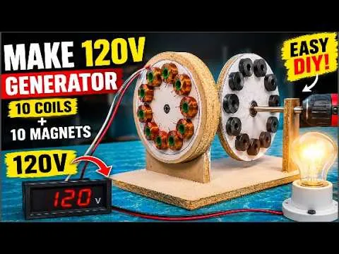
Once the mechanical assembly is complete, electrical testing begins. The two output wires from the stator are connected to a digital voltmeter to measure the generator's output voltage. Instead of using an engine, this demonstration project uses an electric drill to rotate the shaft at a steady speed. As the rotor spins, the alternating north and south speaker magnets move past the stationary copper coils, creating a changing magnetic field. This changing magnetic flux induces an alternating voltage in the coils according to Faraday's Law of Electromagnetic Induction. During testing, the voltmeter reaches approximately 120 volts, demonstrating that the homemade generator successfully converts mechanical rotation into electrical energy. The exact voltage depends on rotor speed, coil winding accuracy, magnet strength, and the precision of the overall construction.
The final demonstration is connecting a light bulb to the generator's output terminals. As the drill spins the rotor, the light bulb illuminates, confirming that the generator is capable of supplying usable electrical power under load. Although this project is designed primarily for educational and experimental purposes, it clearly demonstrates the same engineering principles used in commercial alternators, wind turbines, and hydroelectric generators. Before attempting similar projects, always wear safety glasses, use insulated tools, keep loose clothing away from rotating machinery, and never connect homemade generators directly to household electrical wiring. With proper construction, careful testing, and strict safety practices, this DIY generator becomes an excellent learning tool for students, hobbyists, and engineering enthusiasts who want to understand how electricity is generated through electromagnetic induction.
Safety Tips, Maintenance, and Future Improvements for Your DIY Electricity Generator
Building a homemade electricity generator is an exciting engineering achievement, but operating it safely is equally important. Although this DIY generator demonstrates the principles of electromagnetic induction, it still contains rotating machinery, powerful permanent magnets, sharp tools, and electrical voltage that can present hazards if handled improperly. Before operating the generator, always inspect every component to ensure that the magnets are securely attached, the shaft rotates smoothly, and all electrical connections are insulated. The project concludes by emphasizing that homemade electrical devices should only be used for educational and demonstration purposes and that proper safety equipment should always be worn during construction and testing.
Personal protective equipment should be worn throughout both the construction and testing phases. Safety glasses protect your eyes from flying wood chips, metal fragments, or loose magnets, while insulated gloves reduce the risk of accidental electrical contact during testing. When operating power tools such as drills, saws, or grinders, always secure the workpiece firmly and avoid wearing loose clothing or jewelry that could become caught in rotating machinery. Keep your workspace clean, well-lit, and organized to reduce accidents. Children should never operate the generator without close adult supervision, and inexperienced builders should seek guidance from someone familiar with basic electrical and mechanical safety practices.
Routine maintenance is essential for keeping the generator operating efficiently over time. Before each use, inspect the bearings for smooth rotation and apply lubricant if necessary to reduce friction. Check the adhesive holding the speaker magnets in place and ensure that none have shifted due to vibration. Examine the copper coil connections for loose solder joints, damaged insulation, or corrosion that could reduce electrical performance. Dust, wood particles, and metal debris should be cleaned from the generator regularly because contaminants can interfere with cooling and mechanical movement. Performing these simple maintenance tasks helps maintain consistent voltage output and extends the life of the generator.
Once the basic generator is working successfully, there are many ways to improve its performance and expand its capabilities. Builders can experiment with stronger neodymium magnets, increase the number of coil turns, use thicker copper wire for higher current capacity, or redesign the stator using laminated steel cores to improve magnetic efficiency. Mechanical upgrades such as precision-machined rotors, metal frames, dual-bearing supports, and balanced flywheels can reduce vibration and increase reliability. The generator can also be connected to a bridge rectifier, voltage regulator, battery charging circuit, or inverter for additional educational experiments involving DC power systems and renewable energy applications. Every modification provides valuable hands-on experience with electrical machine design and engineering optimization.
In conclusion, building a DIY electricity generator using 10 speaker magnets and 10 handmade copper coils is an excellent project for anyone interested in renewable energy, electrical engineering, and practical STEM education. It demonstrates the real-world principles of electromagnetic induction while teaching valuable skills in woodworking, mechanical assembly, coil winding, electrical wiring, and performance testing. Although the generator is intended for educational use rather than powering household appliances, it offers an engaging way to understand how mechanical motion is converted into electricity. By following accurate construction methods, performing regular maintenance, and observing all recommended safety precautions, builders can create a reliable demonstration generator while gaining a deeper appreciation for the engineering principles that power modern electrical generation systems.
Frequently Asked Questions (FAQs)
A DIY electricity generator is a homemade device that converts mechanical energy into electrical energy using magnets and copper coils through electromagnetic induction.
As the magnets rotate past stationary copper coils, they create a changing magnetic field that induces electrical voltage according to Faraday's Law.
Old speaker magnets are strong, inexpensive, and easy to recycle, making them ideal for educational DIY generator projects.
This generator uses 10 speaker magnets arranged in alternating north and south polarity.
The generator uses 10 handmade copper coils mounted evenly around the stator.
Use enamel-coated copper wire. The example project uses approximately 0.65 mm wire.
Each coil is wound with approximately 290 turns to produce consistent electrical output.
A 22 mm thick wooden plate is used as the rotor because it is lightweight and easy to machine.
Alternating north and south poles create a changing magnetic field, which is necessary for generating alternating current.
The demonstrated project produces approximately 120 volts when spun at sufficient speed.
A handheld electric drill is commonly used to rotate the generator during testing.
No. This project is designed for educational and demonstration purposes only.
The air gap between magnets and coils should be about the thickness of a sheet of paper.
Bearings reduce friction, improve rotor stability, and allow smooth high-speed rotation.
Yes. Stronger magnets generally increase magnetic flux and can improve voltage output.
You can use stronger magnets, increase coil turns, improve winding quality, or spin the rotor faster.
Yes. Beginners with basic woodworking and electrical knowledge can build this generator by following proper safety procedures.
Wear safety glasses, insulated gloves, and never connect homemade generators directly to household electrical wiring.
Yes, but you should use a suitable rectifier and charge controller to regulate the output safely.
Conclusion
Building a DIY electricity generator using 10 speaker magnets and 10 handmade copper coils is an enjoyable and educational engineering project that demonstrates how electricity is generated through electromagnetic induction. By combining recycled speaker magnets, carefully wound copper coils, a precisely balanced wooden rotor, and a well-aligned stator, you can create a functional generator capable of producing usable electrical power for demonstration purposes. Throughout this project, every stage—from marking the wooden plates and winding identical coils to assembling the rotor, wiring the stator, and testing the finished generator—shows the importance of accuracy, patience, and proper engineering techniques. The project transcript concludes with successful testing, showing approximately 120 volts on a voltmeter and lighting a bulb when the rotor is spun with a drill, demonstrating the generator's ability to convert mechanical energy into electricity.
Although this homemade generator is not intended to replace commercial power systems, it provides an excellent platform for learning the basic principles behind alternators, wind turbines, and hydroelectric generators. Builders gain practical experience in woodworking, mechanical assembly, magnet placement, coil winding, soldering, and electrical measurement while developing a deeper understanding of renewable energy technologies. Whether you are a student, hobbyist, DIY enthusiast, or engineering learner, this project offers valuable hands-on knowledge that can serve as the foundation for more advanced generator designs. Always prioritize safety by wearing protective equipment, using insulated tools, and never connecting homemade generators directly to household electrical systems. With careful construction, regular maintenance, and continued experimentation, this DIY electricity generator becomes an outstanding educational project that inspires creativity, technical skills, and a greater appreciation for the science of electricity generation.
How to Make a 120V Electricity Generator Using 10 Old Speaker Magnets | DIY Homemade Generator
Discussion
No comments yet. Be the first to join the conversation!