
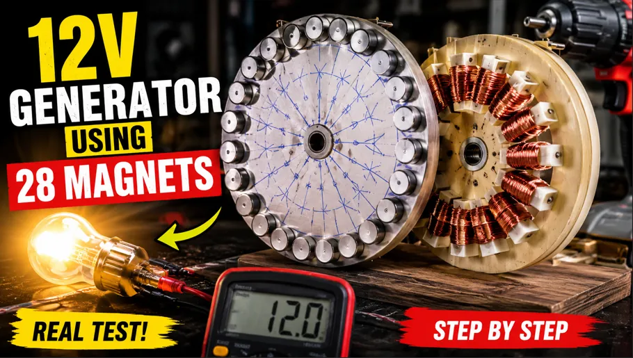
DIY Electricity Generator Using a 7-Inch Grinder Blade and 28 Magnets
Introduction and Basic Concept
Welcome to the DIY Generator Project
Understanding Electromagnetic Induction
The basic principle behind this generator is electromagnetic induction. Whenever a magnetic field changes relative to a conductor such as a copper coil, an electrical voltage can be induced in that conductor. This principle is fundamental to the operation of many generators used around the world. In our homemade design, the magnets are attached around the rotating grinder blade while the copper coils remain stationary on the wooden plate. When the blade rotates, the magnets repeatedly move past the coils. Their changing magnetic field produces an induced voltage in the wire. The amount of electricity generated depends on several factors, including magnetic field strength, number of turns in the coils, coil design, the distance between magnets and coils, and the speed at which the magnetic field changes.
Why Use a Grinder Blade as the Rotor
For this experimental generator, the 7-inch grinder blade serves as the rotating disc or rotor. A grinder blade provides a convenient circular shape that can be marked and divided into equal positions. The flat surface also provides an area where magnets can be arranged around the outer portion of the disc. In a real engineering application, a rotor would normally be specifically designed and balanced for generator operation, but this project demonstrates the concept using an accessible mechanical component. Because the blade rotates at potentially high speed, it is extremely important to treat it as a rotating machine component rather than an ordinary piece of metal. Proper mounting, balance, guarding, secure magnet attachment, and controlled testing are essential considerations throughout the project.
The Role of the 28 Magnets
The generator uses 28 magnets distributed evenly around the rotating blade. The magnets provide the changing magnetic field required for electromagnetic induction. Instead of placing the magnets randomly, we divide the blade into 28 equal sections and install one magnet at each marked position. The magnets are also arranged with alternating polarity, meaning one magnet presents one magnetic pole toward the coils while the next presents the opposite pole. This creates a repeating magnetic pattern as the rotor turns. The purpose of this arrangement is to expose the stationary coils to continuously changing magnetic conditions. The exact electrical output cannot be determined simply from the number of magnets, because generator performance depends on the complete magnetic and electrical design.
The Role of the Fourteen Coils
Fourteen bobbins are installed on the stationary wooden plate and are positioned evenly around the center. These bobbins provide the forms around which enamel-coated copper wire is wound. Each coil contains 100 turns of approximately 0.59 mm enamel-coated copper wire according to the build described in the project. When the rotor spins, the magnetic field from the 28 magnets changes through the nearby coils. This produces an induced electrical voltage in the winding. The relationship between the 28 magnets and 14 coils is important because the magnetic poles and coil positions must interact consistently as the rotor rotates. Although this arrangement can demonstrate electrical generation, the actual connection and phase behavior should be considered carefully when designing a practical generator.
Mechanical Energy Becomes Electrical Energy
One of the most important ideas demonstrated by this project is that the generator does not create energy from nothing. Mechanical energy must be supplied to rotate the rotor. In our test, that mechanical energy is provided by a drill machine. The drill turns the shaft, the shaft turns the grinder blade, the blade moves the magnets past the coils, and the changing magnetic field induces electrical voltage. The electrical energy measured at the output is therefore associated with the mechanical energy being supplied to the rotating system. This is an important distinction when discussing homemade generators because a generator converts energy from one form to another. It does not violate the basic laws of physics or produce unlimited free energy.
What Viewers Will Learn
By following this complete project, viewers can learn several practical concepts at the same time. They can see how a rotor is prepared, how magnets can be distributed around a circular surface, how a shaft connection can be created, how a stationary coil plate can be built, how copper wire is wound into coils, and how a rotating magnetic field can induce electrical voltage. The final testing stage provides a simple way to observe the result using a voltmeter and a light bulb. The project also highlights the importance of accuracy, alignment, mechanical stability, electrical connections, and safety. The purpose is not to present this homemade construction as a replacement for a professionally engineered generator, but to provide an interesting hands-on demonstration of electromagnetic induction.
Preparing the 7-Inch Grinder Blade
Selecting and Inspecting the Grinder Blade
The first practical stage of the project is preparing the 7-inch grinder blade that will become the rotor. Before making any modifications, the blade should be inspected carefully for cracks, deformation, corrosion, or other damage. A damaged disc should not be used for a rotating experiment because centrifugal forces can become significant when a disc spins rapidly. The surface should also be reasonably flat so the magnets can be positioned consistently. We place the blade on a stable work surface and prepare the tools needed for marking. The objective at this stage is not yet to assemble the complete generator, but to establish an accurate foundation for the magnetic rotor. Careful preparation at the beginning makes the later assembly process much easier.
Marking the Center of the Blade
Accurate positioning begins with identifying the center of the grinder blade. The shaft and bush will eventually be installed through this central area, so the center must be identified as precisely as possible. If the shaft connection is not centered, the rotor can rotate unevenly and create vibration. We therefore take time to locate the central point and use it as the reference for all subsequent measurements. A ruler, compass, template, or other suitable measuring tool can be used to establish the center. This small step has a major effect on the quality of the final assembly because the magnets need to rotate in a predictable circular path relative to the stationary coils. Good alignment begins with an accurate center.
Dividing the Blade into 28 Equal Sections
After identifying the center, we divide the outer area of the blade into 28 equal sections. These marks serve as guides for the magnet positions. Equal spacing is important because the magnets need to pass the coils at consistent intervals during rotation. We carefully use a measuring method that allows the 28 positions to be distributed evenly around the circumference. The markings should be clear enough to remain visible during the magnet installation process. Instead of estimating the positions by eye, we take time to check the spacing before moving forward. A small error repeated 28 times can produce an uneven rotor, so accuracy during this stage is more valuable than speed.
Checking the Magnet Positions
Once all 28 marks have been created, we inspect the entire circle before attaching anything. We compare the distances between neighboring marks and make sure the pattern returns correctly to the starting point. This is an excellent stage to correct errors because no adhesive has been applied yet. The objective is to create a symmetrical arrangement around the rotor. The magnets will later occupy these locations, so the marking pattern effectively becomes the blueprint for the magnetic rotor. In a simple experiment, it may be tempting to skip this checking process, but careful preparation helps prevent problems during final assembly. An evenly distributed magnetic pattern can also help reduce mechanical imbalance compared with a randomly positioned arrangement.
Preparing the Blade Surface
Before attaching magnets, the blade surface should be clean and suitable for bonding. Dust, oil, grease, rust, and loose particles can reduce adhesive performance. The selected areas can be cleaned according to the material and adhesive manufacturer's recommendations. The objective is to provide a stable surface where each magnet can be securely attached. Because the magnets will experience forces while the rotor turns, adhesive alone should not be treated casually. The bonding method needs to be appropriate for the materials and expected operating conditions. For educational demonstrations, the safest approach is to keep the rotational speed controlled and use appropriate mechanical guarding. The blade should never be treated as safe merely because it is small.
Understanding Rotor Balance
Rotor balance becomes increasingly important as rotational speed increases. If one side of the grinder blade has slightly more mass than the opposite side, the imbalance can create vibration. Adding 28 magnets also introduces additional mass, so the magnets should be similar in size and weight and positioned as evenly as possible. The completed rotor should be checked for obvious imbalance before attempting a powered test. A professional rotating assembly would normally undergo appropriate balancing and mechanical analysis. In a DIY experiment, keeping the speed low during initial checks and stopping immediately if unusual vibration occurs is essential. Balance is not just about making the project look neat; it directly affects mechanical stability and safety.
Preparing for Magnet Installation
With the 28 positions accurately marked, the grinder blade is ready for the next major stage: installing the magnets. Before applying adhesive, we organize the magnets and decide the polarity sequence. The magnets must be handled carefully because strong magnets can snap together unexpectedly, pinch fingers, damage nearby electronic devices, or become difficult to separate. We can identify their poles and establish an alternating north-south pattern before permanently fixing them. Having the arrangement planned in advance reduces mistakes. Once adhesive is applied, repositioning a magnet may become difficult. This preparation stage therefore connects the measurement work completed on the blade with the magnetic assembly that will form the heart of the generator.
Installing Magnets and Building the Shaft Connection
Positioning the First Magnet
We now begin installing the 28 magnets onto the grinder blade. The first magnet is placed at one of the marked positions and becomes the reference point for the entire sequence. It is important to ensure that the magnet sits at the intended radial distance from the center. If one magnet is significantly closer or farther from the center than the others, the magnetic interaction with the coils will not be consistent. We carefully position the magnet according to the marking and verify its orientation before applying permanent adhesive. This first installation sets the pattern for the remaining magnets, so it is worth taking a little extra time to make sure the reference position is correct.
Creating the Alternating Polarity Pattern
After the first magnet is positioned, the remaining magnets are installed using an alternating polarity arrangement. One magnet faces one pole toward the coils, while the next magnet faces the opposite pole. The sequence continues around the entire blade. This arrangement creates alternating magnetic fields as the rotor rotates. The purpose is to produce repeated changes in magnetic flux through the stationary coils. The pattern should be checked frequently during installation because strong magnets can attract or repel one another and make handling challenging. Rather than assuming every magnet is oriented correctly, we verify the polarity before securing each one. Consistency around the full rotor is essential to the intended experimental design.
Securing the Magnets with Adhesive
Once a magnet is correctly positioned and its polarity has been confirmed, we use a suitable strong adhesive to secure it to the blade. The adhesive should be selected for the materials involved and for the forces expected during the intended test. We apply it carefully so that it bonds the magnet without interfering unnecessarily with the rotating clearance. Each magnet is held in position while the adhesive begins to set. The process is repeated around the blade until all 28 magnets are installed. The adhesive must be given sufficient curing time according to its manufacturer's instructions. Starting the generator before the adhesive has properly cured can allow a magnet to move or detach, creating a serious rotating hazard.
Checking All 28 Magnets
After completing the installation, we inspect every magnet individually. We check that each one is firmly attached, evenly spaced, correctly oriented, and positioned at the same general distance from the center. We also look for excess adhesive that could interfere with the rotor or coils. This inspection provides an opportunity to correct problems before the rotor is connected to the rest of the generator. A simple visual check is not a substitute for proper engineering verification, but it is an important practical step in a small demonstration. The more consistent the magnetic arrangement, the easier it becomes to understand the relationship between rotor movement and the electrical output observed during testing.
Making the Custom Bush
The next stage is creating a custom bush that connects the grinder blade to the rotating shaft. In the project, a lathe machine is used to shape the bush according to the required dimensions. The purpose of the bush is to provide a central mechanical connection between the blade and shaft. Its dimensions need to match the blade's center opening and the shaft used in the experiment. Proper machining is important because an inaccurate bush can introduce runout, vibration, or misalignment. A professional machine shop would measure the components precisely and verify concentricity. For this demonstration, the key concept is that the rotor needs a secure and centered mechanical connection so that rotational force can be transferred smoothly.
Installing the Bush into the Blade
After the bush has been prepared, it is installed into the center hole of the grinder blade. We carefully position it so that its axis aligns with the blade center. Strong adhesive may be used as part of the described construction, but the suitability of adhesive for a high-speed rotating joint depends on the materials, forces, curing conditions, and operating speed. The connection should never be assumed safe simply because it feels secure by hand. Before powered rotation, the assembly needs careful inspection and a controlled low-speed test. The bush is one of the most important mechanical components because it transfers torque from the shaft into the magnet rotor.
Preparing the Completed Rotor
With the bush installed and the magnets secured, the grinder blade has now become the experimental magnetic rotor. We inspect the complete assembly one more time before moving to the wooden coil plate. The magnets form a circular alternating magnetic pattern, while the bush provides the central shaft connection. At this point, the rotor should be handled carefully because the magnets can attract metal objects and the blade itself is a mechanical component intended to rotate. The completed rotor represents the moving side of the generator, while the wooden plate and coils will form the stationary side. Keeping these two systems aligned with an appropriate air gap will be one of the major challenges in the final assembly.
Building the Wooden Plate and Fourteen Bobbins
Preparing the Wooden Plate
The stationary part of our generator begins with a suitable wooden plate. This plate provides the support structure for the 14 winding bobbins. We choose a plate large enough to accommodate the bobbins around the center while maintaining a consistent relationship with the rotating magnets. The surface should be reasonably flat and strong enough for the intended demonstration. Wood is convenient for an educational prototype because it is easy to cut, drill, mark, and modify. However, the final structure still needs to be mechanically stable. The plate must not flex excessively while the rotor is spinning, because changes in the distance between magnets and coils can affect both performance and mechanical clearance.
Drilling the Center Hole
The first major modification to the wooden plate is creating an accurate center hole for the bearing. We carefully mark the center and drill a hole that matches the selected bearing or bearing housing. Center alignment is extremely important because the shaft passing through the bearing must remain concentric with the rotor. If the bearing is offset, the grinder blade may rotate eccentrically relative to the coils. We therefore measure the center carefully before drilling. The hole should be made cleanly and with appropriate support for the wood. After drilling, we test-fit the bearing to ensure it sits correctly without unnecessary movement.
Installing the Bearing
The bearing provides a low-friction support point for the rotating shaft. Once the center hole has been prepared, the bearing is positioned in the wooden plate. Its purpose is to allow the shaft and rotor to rotate while keeping the rotor axis supported. The bearing must be mounted securely and aligned with the shaft. If the bearing is loose, tilted, or poorly supported, the rotor can wobble. In a more advanced design, multiple bearings or a stronger frame could provide additional support. For the educational project, the central bearing demonstrates an important mechanical principle: a generator requires not only electrical components but also a stable mechanical system capable of supporting the rotating assembly.
Marking Fourteen Equal Positions
After preparing the center, we use a compass and measuring tools to mark 14 equal positions around the wooden plate. These positions will hold the winding bobbins. Equal spacing is important because the coils should interact with the passing magnets in a predictable pattern. We take the center of the plate as the reference point and create a circular arrangement. Each marking represents the approximate centerline of one coil. The process is similar to dividing the grinder blade into 28 sections, but now the objective is to create the stationary electrical portion of the generator. Accuracy in this stage helps maintain consistent spacing between coils and prevents one coil from being unnecessarily close to another.
Installing the First Bobbin
Once the 14 locations are marked, we begin placing the bobbins around the wooden plate. The first bobbin becomes a reference for the remaining positions. We make sure it is properly aligned and firmly attached to the plate. The bobbin needs enough space for the copper wire to be wound around it without interfering with neighboring bobbins. Its position relative to the center also needs to match the intended magnetic path. We continue checking the distance from the center as we install each bobbin. The purpose is to create a circular stator assembly where all 14 coils occupy comparable positions around the rotor.
Installing All Fourteen Bobbins
The remaining bobbins are installed one by one using the markings as guides. We carefully maintain equal spacing and consistent orientation. Once all 14 bobbins are positioned, the plate begins to look like the stationary section of a small axial-flux-style experimental generator. Each bobbin will eventually carry a copper winding, and the rotating magnets will pass near the coils. The bobbins should be secured firmly enough to prevent movement during winding and testing. We inspect the complete circle and verify that no bobbin is significantly out of position. This stage is important because a neatly constructed stator makes the subsequent winding process easier to control.
Preparing the Stator for Winding
With all 14 bobbins installed and securely fixed, the wooden stator plate is ready for winding. Before introducing the copper wire, we inspect every bobbin for sharp edges or points that could damage the enamel insulation. We also prepare the wire, tools, and a method for counting turns. The winding process requires patience because each of the 14 coils will receive 100 turns. Keeping the winding neat and consistent is more important than completing it quickly. The completed stator will contain hundreds of individual wire turns distributed across the bobbins. This winding creates the conductive paths through which the induced voltage can be measured during the final generator test.
Winding Fourteen Coils with Copper Wire
Selecting the Copper Wire
For this project, the winding uses approximately 0.59 mm enamel-coated copper wire. The enamel insulation allows adjacent turns of wire to remain electrically separated while still allowing the copper conductor to carry current. Choosing wire involves more than simply selecting a diameter; current capacity, resistance, winding space, insulation quality, temperature, and the intended electrical configuration all matter. In this educational build, the stated wire size provides the basis for the demonstrated winding process. Before starting, we inspect the wire to ensure the insulation is intact. Damaged enamel can create short circuits between turns and affect the electrical behavior of the coil.
Winding the First Coil
We begin with the first bobbin and carefully wrap the copper wire around it by hand. The goal is to create 100 turns on each bobbin. We count the turns carefully rather than estimating them. Maintaining consistent tension helps keep the winding compact and orderly. The wire should be guided around the bobbin without unnecessary crossing or sharp bends. As the turns accumulate, the coil becomes thicker and more defined. This first coil establishes the technique used for all the remaining coils. Taking time to demonstrate the process clearly is useful because viewers can see exactly how a simple piece of copper wire becomes an electrical coil capable of interacting with a magnetic field.
Counting Exactly 100 Turns
Accurate turn counting is an important part of the winding process. According to the project design, every coil contains 100 turns. We count each complete pass around the bobbin and maintain a consistent winding direction. If turns are accidentally skipped or counted twice, the coils may not be identical. In a generator, differences between coils can influence resistance, induced voltage, and overall electrical behavior. We therefore focus on accuracy rather than speed. A simple manual counting method can be used, but recording progress can make the process easier when many coils are involved. After reaching 100 turns, we prepare to continue toward the next bobbin without unnecessarily cutting the wire.
Continuing to the Next Bobbin
One distinctive feature of this project is that the wire is continued from one coil to the next rather than being cut after every individual bobbin. Once the first coil reaches its target number of turns, we guide the wire toward the second bobbin and begin winding again. This creates a continuous winding path through the stator assembly. The exact electrical result depends on how the coils are connected and oriented, so a practical generator should have its winding configuration carefully designed and verified. During construction, the important objective is to maintain the intended winding direction and keep the connecting wire protected from damage as it travels between neighboring bobbins.
Maintaining Consistent Winding Direction
As we continue through the 14 bobbins, maintaining the same intended winding direction becomes very important. The relationship between coil orientation and magnetic polarity affects the induced voltage. If one coil is wound in the opposite direction accidentally, its electrical contribution may oppose rather than reinforce the others, depending on the connection scheme. We therefore pay close attention to the direction in which the wire wraps around every bobbin. The winding should remain tight enough to prevent loose loops but not so tight that the enamel insulation is damaged. Consistency is one of the biggest factors in making a handmade winding look and behave like a deliberately designed electrical assembly.
Completing All Fourteen Coils
The same process is repeated until all 14 bobbins have been wound with 100 turns each. This is a time-consuming stage, but it is also one of the most educational parts of the project. Viewers can see how mechanical preparation and electrical construction come together. The copper wire gradually transforms the simple wooden plate into a stator containing multiple coils. We continue checking the wire tension, coil shape, turn count, and connection path throughout the process. By the time the fourteenth coil is complete, a substantial amount of copper has been arranged around the plate. The completed winding is now ready for inspection and preparation for final generator assembly.
Inspecting the Finished Winding
After completing the fourteenth coil, we carefully inspect the entire winding. We verify that all 14 coils are present, that each contains the intended number of turns, and that the continuous wire remains connected as planned. We also inspect the enamel insulation for visible damage and make sure the winding is firmly seated on the bobbins. The output wires are identified so they can later be connected to a voltmeter or other appropriate test equipment. At this point, the electrical portion of the generator is substantially complete. The rotor contains the magnets, while the stator contains the copper coils. The final challenge is bringing these two parts together with accurate alignment and safe mechanical clearance.
Final Assembly and Electrical Testing
Bringing the Rotor and Stator Together
We now reach the final assembly stage of the DIY generator. The grinder blade carrying the 28 magnets is positioned relative to the wooden plate carrying the 14 coils. The objective is to create a controlled gap between the rotating magnets and stationary coils. The rotor must be able to spin freely without the magnets touching the bobbins, wood, wires, or other components. Alignment is carefully checked from several angles. This is also the stage where the shaft passes through the bearing and the rotor is connected to the mechanical drive. A professional design would use precisely engineered mounts and guards, while this experimental setup requires especially cautious low-speed testing.
Checking Mechanical Clearance
Before connecting a drill machine, we manually inspect the rotor and rotate it slowly if it can be done safely. We check whether the grinder blade remains centered and whether any magnet approaches the stationary components too closely. The clearance should remain consistent throughout a complete revolution. Any rubbing, wobbling, unusual movement, or loose component should be corrected before powered testing. Mechanical clearance is critical because even a small amount of rotor movement can become a larger problem as rotational speed increases. This inspection also provides an opportunity to confirm that the shaft, bearing, bush, rotor, and wooden plate are working together as a stable assembly.
Connecting the Voltmeter
For the electrical test, we connect the generator output wires to a suitable voltmeter. The meter allows us to observe the voltage generated when the rotor spins. The meter should be configured correctly for the expected type of output, and the connections should be secure. Before rotating the generator, we confirm that the leads are not exposed in a way that could cause accidental contact or short circuits. The purpose of this first test is mainly to demonstrate voltage generation rather than to determine the generator's complete power capability. Voltage alone does not tell us how much useful electrical power the generator can deliver under load.
Rotating the Generator with a Drill
We use a drill machine as the mechanical drive for the demonstration. The drill is connected to the generator shaft and used to rotate the magnetic rotor. Initial testing should be performed cautiously at low speed while observing the entire assembly. As the rotor turns, the 28 magnets move past the 14 coils, creating changing magnetic flux through the windings. The voltmeter responds to this induced electrical voltage. The drill is therefore providing the mechanical input energy required for the experiment. The faster the magnetic field changes, the greater the induced voltage can become within the operating limits of the design, although the actual relationship depends on the generator's magnetic and electrical characteristics.
Observing Approximately 12 Volts
During the demonstrated test, the voltmeter shows an output reaching approximately 12 volts. This measurement provides a clear visual indication that the rotating magnetic field and stationary copper coils are interacting to produce electrical voltage. The exact voltage observed in a homemade generator can vary significantly with rotational speed, magnet strength, coil geometry, air gap, wiring configuration, measurement method, and other factors. Therefore, the approximately 12-volt result should be understood as a test observation rather than a guaranteed specification for every identical construction. Nevertheless, seeing voltage appear on the meter is an effective demonstration of electromagnetic induction in action.
Understanding Why Speed Matters
The output voltage of an electromagnetic generator is strongly related to how quickly magnetic flux changes through its coils. When the rotor turns faster, the magnets pass the coils more rapidly, causing the magnetic field experienced by the windings to change more quickly. This can increase the induced voltage within the limits of the design. When the rotor slows down, the voltage may decrease. This is why the drill speed can influence the reading observed on the voltmeter. However, increasing speed is not automatically better. Mechanical components, adhesives, magnets, bearings, shafts, and blades all have limits. Safe operation must always take priority over obtaining a higher voltage reading.
What the First Test Demonstrates
The first test provides the central result of the project: mechanical rotation can produce measurable electrical voltage when magnets and coils are arranged correctly. The drill supplies mechanical energy, the shaft transfers that energy to the grinder blade, the blade rotates the magnets, and the changing magnetic field induces voltage in the copper coils. The approximately 12-volt reading provides a simple experimental confirmation of this process. This does not mean the generator can automatically provide unlimited electricity or operate without mechanical input. Instead, it demonstrates a well-established physical principle that is used in everything from small alternators to large electrical power stations.
Light Bulb Test, Safety, Conclusion, and Educational Value
Connecting the Light Bulb
After completing the voltage measurement, we perform another simple demonstration by connecting a suitable light bulb to the generator output. The electrical connections are checked carefully before the rotor is turned again. The bulb provides a visual indication that the generator can deliver electrical energy to a load under the demonstrated conditions. A voltmeter measures electrical potential, while a load such as a bulb allows us to observe energy transfer more directly. The bulb and generator must be electrically compatible, and the expected voltage and current should be considered before making the connection. Once everything is secure, we prepare to rotate the generator again using the drill machine.
Watching the Bulb Glow
When the drill rotates the generator, the magnets again move past the coils and induce electrical voltage in the winding. As the generated electricity reaches the connected bulb, the bulb begins to glow. This provides a satisfying visual conclusion to the construction process because the mechanical movement has produced an observable electrical effect. The brightness of the bulb can change depending on rotational speed and the electrical characteristics of both the generator and bulb. A brighter bulb does not necessarily mean the generator is highly efficient, because useful electrical power depends on voltage, current, losses, and mechanical input. Still, the glowing bulb is an excellent educational demonstration of electromagnetic induction.
Understanding Voltage Versus Power
One important lesson from the final test is the difference between voltage and electrical power. Seeing approximately 12 volts on a meter does not automatically mean the generator can supply a large amount of electricity. Power depends on both voltage and current, commonly expressed as the relationship between electrical power, voltage, and current. A generator may produce a measurable open-circuit voltage while being unable to maintain that voltage under a significant load. Internal resistance, coil resistance, magnetic strength, wire size, rotational speed, and mechanical losses all affect the result. Therefore, the 12-volt measurement should be presented honestly as a voltage observation, while further testing would be needed to determine current capability, output power, and efficiency.
Why the Generator Works
The generator works because relative motion exists between the magnetic fields produced by the magnets and the copper conductors in the coils. As the 28 magnets rotate, the magnetic flux through the stationary coils continuously changes. According to Faraday's law of electromagnetic induction, a changing magnetic flux induces an electromotive force in a conductor. The alternating polarity arrangement increases the frequency of magnetic changes experienced by the coils as the rotor turns. The resulting electrical output can then be measured or used to operate an appropriate load. This simple experiment connects a practical homemade device to one of the most important principles in electrical engineering and demonstrates why generators require mechanical movement to produce electrical energy.
Safety and Responsible Experimentation
Safety is one of the most important parts of this project. The grinder blade and attached magnets become rotating components, and a failure at high speed can be dangerous. Strong magnets can pinch fingers and interfere with electronic devices. Drilling, cutting, machining, adhesives, copper wire, and electrical connections also present different hazards. Anyone attempting a similar experiment should understand the tools and materials involved, use appropriate personal protective equipment, keep hands and loose clothing away from rotating components, and avoid operating an unguarded rotor at excessive speed. Electrical testing should also be performed carefully, with appropriate instruments and insulated connections. This project is presented for educational and experimental purposes, not as a recommendation for unsafe high-speed construction.
Final Results and What We Learned
After completing the rotor, installing 28 alternating-polarity magnets, preparing the custom bush, building the wooden stator, installing 14 bobbins, winding 100 turns on each coil using approximately 0.59 mm enamel-coated copper wire, and assembling the complete system, we successfully demonstrate electrical generation. The drill-powered test produces approximately 12 volts in the described experiment, and the connected light bulb glows when the generator is rotated. The project demonstrates the complete energy-conversion chain from mechanical input to electrical output. More importantly, it shows that generator construction involves many interconnected factors: magnetic arrangement, coil winding, mechanical alignment, rotor balance, rotational speed, electrical connections, and load characteristics.
Conclusion and Thanks for Watching
And that brings us to the end of today's DIY electricity generator project. We started with a simple 7-inch grinder blade and transformed it into an experimental magnetic rotor by adding 28 magnets in an alternating polarity pattern. We then prepared a wooden stator with 14 evenly spaced bobbins and wound each coil with 100 turns of approximately 0.59 mm enamel-coated copper wire. After completing the mechanical assembly, we used a drill machine to rotate the rotor and observed approximately 12 volts on the meter. We then connected a light bulb and watched it glow, demonstrating the transfer of generated electrical energy to a load. This experiment provides a practical introduction to electromagnetic induction and shows how mechanical rotation can be converted into electrical energy. If you enjoyed the project, make sure to like the video, subscribe to the channel, and share it with your friends. Thanks for watching, stay safe, and we will see you in the next DIY experiment
I Made a 12V Electricity Generator Using a 7 Inch Grinder Blade & 28 Magnets!
Discussion
No comments yet. Be the first to join the conversation!