
How to Build a Powerful 600W Inverter at Home Using Simple Components
Building a homemade inverter is one of the most useful electronics projects for hobbyists, students, and technicians who want a reliable backup power solution during electricity outages. A 600W inverter can easily power small appliances, LED bulbs, fans, chargers, and other essential devices. In this detailed guide, you will learn how to build a powerful 600W inverter using a microwave transformer, 2SC5200 transistors, MOSFETs, resistors, capacitors, and simple winding techniques. This project is cost-effective, practical, and ideal for anyone interested in DIY electronics.
This inverter project focuses on using easily available components while maintaining good performance and efficiency. The transformer winding process, transistor arrangement, resistor connections, and capacitor installation all play an important role in ensuring stable operation. By carefully following the assembly process, you can create a reliable inverter that delivers excellent results during power failures.
The advantage of making your own inverter is that it helps you understand the working principles of power electronics while also saving money compared to commercial inverter systems. The use of a microwave transformer makes this project both affordable and efficient. Additionally, the 2SC5200 transistors provide strong switching performance and can handle the load effectively when mounted with proper heat sinks.
Another major benefit of this inverter design is that the components are commonly available in local electronics markets. This means you do not need expensive or rare parts to complete the setup. The project is suitable for beginners who want to improve their soldering and circuit assembly skills as well as experienced electronics enthusiasts looking for a practical inverter solution.
In this article, we will explain every major step involved in building the inverter, including transformer preparation, transistor assembly, resistor and capacitor wiring, power supply connections, testing procedures, and safety measures. By the end of this guide, you will have a complete understanding of how to build and operate a 600W inverter successfully.
Preparing the Transformer for the 600W Inverter
The transformer is the heart of this inverter project because it converts low-voltage DC power from the battery into high-voltage AC output. To begin the process, the transformer core must first be prepared carefully using insulating paper. This insulation layer is extremely important because it prevents short circuits between the winding and the transformer body. A properly insulated transformer ensures long-term reliability and safe operation.
Once the insulation paper is applied evenly over the transformer core, the winding process can begin. Copper wire with a thickness of approximately 1.829 mm is used to create the winding. This wire thickness is suitable for handling the required current and power for a 600W inverter setup. Proper wire selection improves efficiency and reduces unnecessary heating during operation.
The transformer winding is completed by winding 17 turns on one side and another 17 turns on the opposite side. This creates a 12 + 0 + 12 volt winding configuration. Maintaining equal turns on both sides is essential because it helps produce balanced voltage output. While winding the wire, proper tension should be maintained to keep the turns neat, close together, and evenly arranged.
After the winding process is complete, the transformer output voltage should be tested using a multimeter. During testing, the transformer typically produces around 14 + 14 volts when no load is connected. This slightly higher voltage is normal and confirms that the winding has been completed correctly. Stable readings indicate that the transformer is ready for use in the inverter circuit.
A properly prepared transformer greatly affects the performance and efficiency of the inverter. Poor winding techniques can lead to overheating, voltage imbalance, and reduced output power. Therefore, taking time to wind the transformer carefully is one of the most important steps in building a successful inverter system.
Assembling the 2SC5200 Transistors and Heat Sinks
The next stage of the inverter project involves assembling the power transistors and heat sinks. Four 2SC5200 transistors are used in this design because these transistors are capable of handling high current and switching loads efficiently. Since transistors generate heat during operation, proper cooling is required to maintain stable performance and extend component life.
Each 2SC5200 transistor should be mounted securely onto a separate heat sink. Proper thermal contact between the transistor and heat sink is necessary for effective heat dissipation. In some cases, insulating pads may also be required to avoid unwanted electrical contact between the transistor body and the heat sink surface. Tightening the screws firmly ensures that the transistors remain stable during operation.
After mounting the transistors onto heat sinks, the entire assembly should be arranged neatly on a wooden base. A wooden plate is often used because it provides electrical insulation while also keeping all components organized. A clean and organized layout makes wiring easier and improves safety during inverter operation.
The emitter pins of all transistors are then bent carefully upward and connected together using a suitable wire. This common emitter connection is an essential part of the inverter circuit. The soldering must be done carefully to ensure strong and stable joints. Loose or weak solder connections can create resistance, overheating, and poor inverter performance.
Next, the transistor base pins are connected in pairs, followed by the collector pins. These grouped connections allow the transistors to work together efficiently within the circuit. Proper transistor assembly and wiring are critical because the power stage is responsible for generating the switching action required to produce AC output from the DC battery supply.
Connecting Resistors, Capacitors, and Transformer Wiring
Once the transistor assembly is completed, the resistor connections are added to stabilize and control the circuit operation. Four 1K resistors are used in this inverter design. Two resistors are connected together to form one pair, and the remaining two resistors form another pair. These resistor networks help regulate transistor switching and improve circuit stability.
One side of the resistor pair is connected to the collector terminals of one transistor group, while the opposite side is connected to the base connection of the opposite transistor pair. This arrangement creates the necessary feedback mechanism for the inverter oscillator circuit. Proper resistor placement is important because incorrect connections can prevent the inverter from functioning.
The second resistor pair is connected in the same way to the remaining transistor group. During soldering, it is important to ensure that all resistor connections are firm and free from loose joints. Stable resistor connections improve signal flow and contribute to reliable inverter operation.
A 1µF 1000V capacitor is then installed between the collector connections of both transistor groups. This capacitor helps stabilize the inverter circuit and improve switching performance. Capacitors in inverter circuits are commonly used for filtering, timing, and maintaining balanced operation. Proper capacitor polarity and secure soldering are important for safety and efficiency.
After completing the resistor and capacitor installation, the transformer winding wires are connected to the collector terminals of the transistor groups. One transformer wire is connected to one transistor pair, while the second wire is connected to the opposite pair. These transformer connections allow the switching transistors to drive the transformer and generate AC voltage output.
Connecting the Battery Supply and Testing the Inverter
With the circuit assembly complete, the next step is connecting the 12V battery supply. The negative battery wire is connected to the common emitter connection of all four transistors. This forms the ground connection for the inverter circuit and completes the negative power path.
The positive battery wire is connected to the center tap of the transformer winding, which is the middle point of the 12 + 12 volt winding configuration. This center-tap connection is extremely important because it distributes power evenly across both sides of the transformer winding. Incorrect battery wiring can damage the circuit, so careful checking is necessary before powering the inverter.
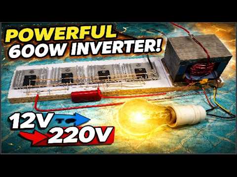
Once the battery is connected properly, the inverter can be tested using a 220V light bulb. The light bulb wires are connected to the transformer output terminals. When the 12V battery supply is switched on, the bulb should light up if the inverter is functioning correctly. This simple test confirms that the inverter is successfully converting DC voltage into AC output.
During testing, the inverter should be observed carefully for unusual sounds, excessive heating, or unstable operation. Heat sinks should remain within safe temperature limits, and all wiring connections should stay secure. If overheating occurs, additional cooling or improved soldering may be required.
Successful testing demonstrates that the inverter is capable of powering small appliances such as bulbs, fans, chargers, and other household devices. This makes the inverter extremely useful during power outages and emergency situations. A properly assembled inverter can provide reliable service for many years with regular maintenance and careful operation.
Safety Tips and Benefits of a DIY 600W Inverter
Safety is one of the most important aspects of working with inverter circuits and electrical equipment. Since inverters generate high voltage AC output, proper insulation and careful handling are essential. Always ensure that all wires are tightly connected and that there are no exposed conductors that could cause electric shock.
Using quality heat sinks is another critical safety measure because transistors generate heat during operation. Good heat dissipation improves efficiency and extends the lifespan of the components. Without proper cooling, transistors may overheat and fail under heavy loads. Adding cooling fans can further improve inverter performance during continuous operation.
One of the biggest advantages of this DIY 600W inverter project is affordability. Commercial inverters with similar power ratings are often expensive, while this homemade version can be built using inexpensive and locally available components. This makes it an excellent option for students, hobbyists, and individuals living in areas with frequent power outages.
Another important benefit is educational value. Building an inverter from scratch helps users understand transformer winding, transistor switching, oscillator circuits, and power conversion principles. This practical knowledge is extremely useful for electronics learning and future DIY power projects.
In conclusion, this 600W inverter project is an excellent example of how simple components can be combined to create a reliable and efficient power backup solution. By carefully following the transformer winding process, transistor assembly steps, resistor and capacitor wiring, and testing procedures, anyone can successfully build a powerful inverter at home. With proper safety measures and maintenance, this inverter can provide stable performance and dependable backup power for a long time.
Frequently Asked Questions (FAQs) About 600W Inverter
| No. | Question | Answer |
|---|---|---|
| 1 | What is a 600W inverter used for? | A 600W inverter is used to convert 12V DC battery power into 220V AC power for running small household appliances such as fans, LED bulbs, chargers, and TVs. |
| 2 | Which transformer is used in this inverter project? | This project uses a microwave transformer with a custom 12 + 0 + 12 winding configuration for efficient power conversion. |
| 3 | Why are 2SC5200 transistors used in the inverter? | 2SC5200 transistors are high-power transistors that provide strong switching performance and can handle heavy loads efficiently. |
| 4 | How many turns are required for the transformer winding? | The transformer requires 17 turns on each side to create the 12 + 12 volt winding configuration. |
| 5 | What battery is required for this inverter? | A 12V battery is required to power the inverter circuit and provide DC input voltage. |
| 6 | Why are heat sinks important in the inverter circuit? | Heat sinks help dissipate heat generated by the transistors, preventing overheating and improving inverter reliability. |
| 7 | Can this inverter run household appliances? | Yes, this inverter can run small appliances like bulbs, fans, chargers, and other low-power devices within the 600W limit. |
| 8 | What is the purpose of the capacitor in the circuit? | The capacitor stabilizes the inverter circuit and improves switching performance for smoother output operation. |
| 9 | Is this inverter project suitable for beginners? | Yes, this project is suitable for beginners with basic electronics and soldering knowledge who want to learn inverter construction. |
| 10 | What safety precautions should be followed while using the inverter? | Always ensure proper insulation, tight wiring connections, good heat sink cooling, and avoid touching exposed wires during operation. |

Discussion
No comments yet. Be the first to join the conversation!