
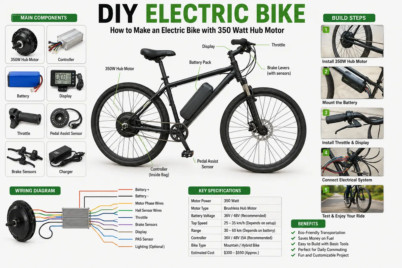
DIY Electric Bike: How to Make an Electric Bike with a 350 Watt Hub Motor
A ground-up, step-by-step DIY electric bike conversion guide: install a 350 watt hub motor, wire the controller correctly, mount a lithium battery safely, and understand the real engineering behind every wire you connect.
Copper loops show winding positions; dashed motion represents alternating phase current, not literal wire paths.
1. Introduction
A DIY electric bike is exactly what it sounds like: an ordinary pedal bicycle that's been fitted with an electric drive system — a motor, a battery, a controller, and the wiring to tie them together — instead of being bought as a factory-built ebike. The appeal is straightforward. You keep the frame geometry, saddle, and gearing you already know, and you add power on top of it, usually for a fraction of what a comparable off-the-shelf ebike costs.
People convert bicycles for a mix of practical and personal reasons. Some want to flatten out a hilly commute without arriving at work drenched in sweat. Some are extending the range of an aging knee or a bad back that makes long rides painful. Others simply enjoy the process — understanding how a brushless motor spins, how a controller times its switching, and how a battery delivers current is genuinely satisfying to build with your own hands.
This guide focuses on the 350 watt hub motor conversion, which sits in a sensible middle ground. It's powerful enough to noticeably help on hills and headwinds, light enough to keep the bike's handling close to normal, and in many regions it stays inside the power ceiling that separates a "pedal-assist bicycle" from a "moped" in the eyes of local traffic law. A hub motor conversion is also mechanically simpler than a mid-drive conversion: the motor lives inside the wheel itself, so there's no need to modify the bottom bracket, chainring, or drivetrain.
This article explains the engineering behind each step and gives realistic performance numbers. It intentionally avoids inflated speed or range claims — actual results depend on your battery, your weight, your terrain, and how the controller is configured, all covered in detail below.
2. Understanding a 350 Watt Hub Motor
Almost every hub motor sold for ebike conversions today is a brushless DC motor, or BLDC. Understanding what's physically happening inside that metal shell makes every later step — wiring, programming, troubleshooting — much easier to reason through instead of memorizing.
How a BLDC hub motor works
A BLDC hub motor is an "outrunner" design: unlike a typical motor where a spinning shaft sits inside a stationary housing, here the outer shell of the motor itself rotates around a fixed core, and the wheel is bolted directly to that rotating shell. Six main parts make this happen:
- Rotor — the outer shell of the motor, permanently bonded to a ring of magnets on its inner surface. This is the part that physically spins and drives the wheel.
- Stator — the fixed core in the center, built from stacked laminated steel teeth. It never rotates; it holds the copper windings.
- Permanent magnets — arranged in alternating north/south polarity around the inside of the rotor shell, usually neodymium for their high magnetic strength relative to weight.
- Copper windings — insulated copper wire wound around each stator tooth in three separate groups (phases), which is why hub motors have three thick "phase wires" coming out of the axle.
- Hall sensors — three small chips mounted on the stator that detect the passing magnets and report rotor position back to the controller many times per revolution.
- Bearings and axle — a fixed steel axle passes through the center and is clamped into the bike's dropouts; sealed bearings let the rotor spin smoothly around it.
The electromagnetic principle at work
The controller feeds current into the three phase windings in a precise, repeating sequence. Each time a winding is energized, it becomes a temporary electromagnet, and it either attracts or repels the nearest permanent magnets on the rotor, depending on polarity. By switching which winding is energized in sync with the rotor's position — information it gets from the hall sensors — the controller keeps a rotating magnetic field just slightly ahead of the rotor's magnets, and the rotor chases it around in a continuous circle. This is the same underlying principle, electromagnetic force between a current-carrying conductor and a magnetic field, that runs every electric motor from a cordless drill to a subway train; a hub motor is simply built as a ring instead of a cylinder so it can double as the wheel hub.
Geared vs direct-drive hub motors
| Feature | Geared hub motor | Direct-drive hub motor |
|---|---|---|
| Internal mechanism | Small high-speed motor drives wheel through a planetary gear reduction | Rotor is bolted straight to the wheel; no gearing |
| Weight | Lighter, typically 2.5–3.5 kg | Heavier, typically 4–6 kg |
| Freewheeling | Freewheels when unpowered, like a normal wheel | Some resistance ("cogging") when pedaling unpowered |
| Regenerative braking | Not possible | Possible with a compatible controller |
| Best suited for | Lightweight builds, hilly routes, easier pedaling when battery is empty | Simpler builds, riders who want regen braking, flatter terrain |
For a first 350W build, most DIYers choose a geared hub motor, because the lighter weight and normal freewheeling behavior make the bike feel closer to a standard bicycle when the motor isn't engaged.
3. Components Required
Below is the full parts list for a 350W hub motor conversion, with typical specifications, rough cost ranges (parts pricing varies by region and supplier), and what to look for when buying.
| Component | Purpose | Typical spec | Est. cost (USD) | Buying tip |
|---|---|---|---|---|
| 350W hub motor | Provides propulsion | 36V, geared, laced to a 26"/27.5"/700c rim | $90–160 | Buy pre-laced into a rim matching your bike's wheel size and brake type |
| Bicycle frame | Structural base for the whole build | Steel or aluminum, disc-brake dropouts preferred | Varies / existing bike | Check dropout width matches the motor's axle |
| Rim | Holds the tire, usually pre-built with the motor | Double-wall alloy, matched spoke count | Included with motor kit | Double-wall rims handle motor torque better than single-wall |
| Spokes | Transfer motor torque from hub to rim | 13g–12g steel, laced 3-cross | $15–30 (if lacing yourself) | Thicker gauge spokes resist torque-related breakage |
| Motor controller | Converts battery DC into timed phase switching for the motor | 36V, 15–20A continuous | $30–60 | Match current rating to motor wattage, not just voltage |
| Lithium battery | Energy storage and current supply | 36V, 10–15Ah, 18650/21700 cells | $180–350 | Buy from a seller who states the BMS current rating, not just capacity |
| Battery charger | Recharges the pack safely | 42V output (for a 36V pack), 2A | $20–40 | Must match your pack's voltage and connector type exactly |
| Display | Shows speed, battery level, assist level, errors | LCD/LED, matched connector (typically 5-pin) | $15–35 | Confirm connector pin-out matches your controller brand |
| Throttle | Manual power request input | Half-twist or thumb throttle, Hall-effect | $8–18 | Half-twist gives finer control; thumb throttle is easier to modulate at low speed |
| PAS sensor | Detects pedaling to trigger assist | Magnetic disc, 8–12 magnets | $10–20 | More magnets = smoother, faster assist engagement |
| Brake sensors | Cuts motor power the instant a brake lever is pulled | Magnetic reed switch, inline with brake lever | $8–15 per pair | Essential for safety — don't skip these |
| Torque arms | Prevents axle from spinning loose in the dropout | Steel, sized to axle flat width | $10–20 | Mandatory above ~250W; buy two for redundancy |
| Wiring harness | Connects motor, controller, and accessories | 18–14 AWG, weatherproof connectors | Often included with controller | Keep spare harness on hand in case of chafe damage |
| Connectors | Joins wiring segments and battery to controller | XT60 / Anderson-style, rated 30A+ | $5–15 | Choose connectors rated above your peak current draw |
| Fuse | Protects wiring from short-circuit current | Inline blade fuse, 20–30A | $3–8 | Size the fuse just above your controller's peak current |
| Battery mount | Secures battery to frame | Bottle-cage bolt-on or frame bag | $15–30 | Choose a mount rated for the pack's actual weight |
| Cable ties | Route and secure wiring along the frame | UV-resistant nylon | $3–6 | UV-rated ties resist cracking in sunlight over time |
| Waterproof heat shrink | Seals wire splices against moisture | Adhesive-lined, 3:1 shrink ratio | $6–12 | Adhesive-lined shrink outperforms plain shrink tube outdoors |
| Tools required | Assembly and diagnostics | Hex keys, cone wrenches, multimeter, crimpers, soldering iron, torque wrench | $40–100 (if not already owned) | A multimeter is non-negotiable for safe wiring checks |
Buy the motor, controller, and battery from the same kit or seller whenever possible. Voltage, connector types, and current ratings are far more likely to match out of the box, which saves you from splicing adapters later.
4. Choosing the Right Bicycle
Not every bicycle is a good conversion candidate. A few structural details determine whether a frame will hold up to motor torque and battery weight over time.
Steel vs aluminum frame
Steel frames flex slightly under load and tend to be more forgiving of stress concentration around the dropouts, which is exactly where hub motor torque is applied. Aluminum frames are lighter and stiffer but can develop fatigue cracks at the dropout over years of hard motor torque if a torque arm isn't fitted. Either material works for a 350W build as long as torque arms are installed — steel just has a slightly larger margin for error.
Wheel size
350W hub motors are commonly available for 26", 27.5", 700c, and 20" wheels. Smaller wheels give more torque at the tire contact patch for the same motor, which helps on hills; larger wheels roll more efficiently and reach a given top speed with less current. Match the motor to your existing wheel size unless you're building the wheel from scratch.
Weight limits
Check the frame and rack manufacturer's stated rider and cargo weight limits, then add the motor (2.5–6 kg), battery (2–4 kg), and mounting hardware. A frame rated conservatively for a standard rider may be pushed close to its limit once motor and battery weight are added, especially on rear rack-mounted battery setups.
Disc brake compatibility
A hub motor conversion adds meaningful weight and speed capability, both of which increase stopping distance. Disc brakes handle this far better than rim brakes because they aren't affected by rim heat buildup or wet-weather performance loss. If your donor bike has rim brakes, budget for a disc brake upgrade, or at minimum fit high-quality brake pads and inspect rim wear closely.
Suspension considerations
A front suspension fork adds compliance but also adds a second consideration: some suspension forks aren't rated for the added stress of a heavier front hub if you're motorizing the front wheel. Most 350W conversions use a rear hub motor specifically to avoid this issue and to keep steering feel closer to normal.
5. Installing the Hub Motor
This is the most mechanically involved part of the build. Work on a bike stand or flip the bike upside-down on a padded surface so both wheels are accessible.
- Remove the old wheel. Release the brake, open the quick-release or axle nuts, and take out the original wheel. Transfer the tire, tube, and disc rotor (if fitted) from the old wheel to the new motor wheel — most kits ship the motor already laced into a bare rim.
- Install the hub motor wheel. Slide the motor's axle into the dropouts, seating the axle flats fully against the dropout faces so they can't rotate. Loosely thread the axle nuts by hand before tightening anything fully.
- Fit the torque arms. Slide the torque arm over the axle flat on each side, positioning it so it braces against the frame or fork blade, then tighten its clamp bolt. This is what actually resists the motor's reaction torque — the axle nuts alone are not enough.
- Check axle alignment. With the wheel centered in the frame, tighten the axle nuts to the torque spec in your motor's manual (commonly 35–45 Nm), alternating sides to keep the wheel centered as you tighten.
- Route the phase and sensor cable. Run the motor's cable along the chainstay or seatstay toward the controller location, keeping it away from the chain, cassette, and any pinch points, and secure it every 8–10 cm with cable ties.
- Center the wheel in the frame. Spin the wheel and sight the gap between tire and frame/fork on both sides; adjust axle nut tension evenly until the gap is equal.
- Adjust the brakes. Re-fit and adjust the brake caliper (disc) or brake pads (rim) to the new wheel, confirming even, rub-free rotation through a full spin.
- Run a no-power safety check. Before connecting any electronics, spin the wheel by hand for at least 10 full rotations to confirm smooth movement, no rubbing, no unusual grinding, and no play in the axle when you gently rock the wheel side to side.
Never skip the torque arm. A hub motor's reaction torque is applied every time you use the throttle or assist, and over weeks of riding an unsecured axle can slowly work its way loose or crack a standard dropout slot.
6. Installing the Battery
Battery placement affects both handling and safety. The three common mounting spots are the main triangle (in place of a water bottle), a rear rack, or a frame bag. Main-triangle mounting keeps weight low and central, which is best for handling.
For center of gravity, aim to keep the battery as low and as close to the bike's midpoint between the wheels as practical. A battery mounted high and far back (like on top of a rear rack) raises the center of gravity and can make the bike feel less stable at speed or when cornering.
Mounting technique depends on the battery's housing: bottle-cage-style packs bolt directly to existing bottle bosses, while rectangular packs typically come with a dedicated bracket that bolts to the frame or rack, with the battery sliding in and locking with a key.
For battery protection, most packs use an aluminum or hard plastic case that resists impacts and road debris; avoid mounting the pack where it could be struck by a pedal, kicked by a passing foot, or scraped against curbs.
Water resistance on most conversion-kit batteries is limited to splash protection — check the specific IP rating before assuming the pack can handle heavy rain or a wash-down.
Fuse installation is a mandatory step, not an optional one: wire an inline fuse directly into the positive lead between the battery and the controller, as close to the battery terminal as possible, so a short anywhere downstream blows the fuse before it can overheat the battery's own wiring.
Size the fuse just above your controller's rated peak current (for example, a 20A controller commonly pairs with a 25–30A fuse) so normal acceleration current doesn't nuisance-trip it.
7. Wiring the Electrical System
A 350W hub motor conversion has a fairly standard wiring map. Understanding what each wire does makes it much easier to diagnose a problem later.
| Wire / connector | Function | Notes |
|---|---|---|
| Battery positive (+) | Supplies main DC current to the controller | Runs through the inline fuse before reaching the controller |
| Battery negative (−) | Return path to the battery's BMS | Never bond this to the frame as a "ground" — ebike systems are floating DC, not chassis-grounded |
| Motor phase wires (3x) | Carry switched current to the stator windings | Usually thick gauge, color-coded, must match controller phase order |
| Hall sensor wires (5x) | Report rotor position to the controller | 5V, ground, and three hall signal lines — usually a single small connector |
| Throttle | Sends a variable voltage signal requesting power | Typically 0.8–4.2V signal range on a 5V supply |
| Brake cutoff | Interrupts motor power when a brake lever is pulled | Wired in-line with the brake lever's magnetic sensor |
| Display | Two-way data link showing status and accepting setting changes | Usually a single multi-pin connector, brand-specific pinout |
| PAS sensor | Sends a pulse signal as the crank rotates, triggering assist | 3-wire: power, ground, signal |
| Lighting output | Switched 12V (or battery voltage) output for a headlight/taillight | Not present on all controllers — check before wiring lights |
Connector types and insulation
Most kits use bullet connectors for the three phase wires, a small keyed connector for hall sensors, and either an XT60 or Anderson-style connector for the main battery leads. Always insulate any exposed splice with adhesive-lined heat shrink rather than electrical tape alone — tape degrades with vibration and UV exposure, while heat shrink stays sealed.
Never connect or disconnect the main battery connector while the controller is powered on. Hot-plugging a high-current connector under load can pit the connector's contacts and, in rare cases, cause a spark near the battery terminals.
8. Programming the Controller
Most 350W controllers expose a handful of adjustable parameters, either through the display's settings menu or through a USB programming cable and configuration software.
// typical adjustable controller parameters
Speed limit (km/h)        : 25   // capped by local regulation in many regions
Current limit (A)         : 15   // should not exceed controller/motor rating
Low voltage cutoff (V)    : 30   // protects a 36V pack from over-discharge
Regen braking             : off  // only valid on direct-drive motors
Throttle start voltage (V): 0.9
Throttle response         : medium
PAS levels                : 5    // number of selectable assist steps
- Speed limit — many controllers let you cap top assisted speed; set this to match your local low-power ebike classification if one applies.
- Current limit — should sit at or below both the controller's and motor's continuous current ratings, never above either.
- Low voltage cutoff — set according to your battery chemistry and cell count so the controller stops drawing power before individual cells are driven into over-discharge.
- Regenerative braking — only functions on a direct-drive hub motor; enabling it on a geared motor does nothing because the rotor isn't mechanically linked when unpowered.
- Throttle sensitivity — a gentler response curve is safer for new riders, especially at low speed and in traffic.
- PAS levels — more levels give finer control over how much the motor contributes relative to your own pedaling effort.
Not every 350W controller supports USB programming. Basic units only expose settings through the display menu, which is usually sufficient for a first build.
9. Testing the Bike
Before riding on the road, work through this bench-test sequence with the bike on a stand so the wheel can spin freely.
- Check voltage. Measure the battery's resting voltage with a multimeter and confirm it's within the pack's normal range (roughly 39–42V resting for a fully charged 36V pack).
- Check motor rotation. With the wheel elevated, apply light throttle and confirm the wheel spins smoothly in the correct direction without hesitation or jerking.
- Test the brakes. Pull each brake lever individually while applying throttle and confirm the motor cuts power instantly every time.
- Monitor controller temperature. After a few minutes of throttle testing, the controller housing should feel warm, not hot to the touch — if it's uncomfortably hot, the current limit may be set too high.
- Check battery performance under load. Watch for excessive voltage sag on the display while applying throttle; some sag is normal, but a steep drop suggests a weak connection or aging pack.
- Listen for unusual noise. Grinding, clicking, or rhythmic ticking noises usually point to a rubbing brake, loose spoke, or bearing issue that should be fixed before riding.
- Check for vibration. Hold the handlebars and frame while running the motor at low speed on the stand; noticeable vibration can indicate an unbalanced wheel or a loose motor mount.
- Road test gradually. Start in a quiet, flat, traffic-free area, testing throttle response, braking, and pedal-assist engagement at low speed before moving to normal riding conditions.
10. Battery Safety
Lithium-ion cells store a large amount of energy in a small space, which is exactly what makes them useful for ebikes and exactly why they demand careful handling.
Lithium-ion chemistry basics
Most ebike packs use 18650 or 21700 cylindrical cells built around lithium-based cathode chemistries (commonly NMC or LFP). Each cell nominally sits around 3.6–3.7V (or 3.2V for LFP), and cells are wired in series to reach the pack's working voltage — ten cells in series gives roughly 36V nominal.
Charging safety
Always use the charger specified for your exact pack voltage and chemistry, charge on a non-flammable surface, and avoid leaving a charging pack unattended overnight, especially with lower-quality cells or an unbranded BMS.
Storage
For storage longer than a few weeks, keep the pack around 50–60% charge rather than fully charged, in a cool, dry location away from direct sunlight.
Temperature limits
Avoid charging a pack that's below roughly 0°C (32°F) or has just come in from freezing conditions — charging cold lithium cells can cause internal lithium plating, which permanently reduces capacity and can create an internal short over time.
Over-current and over-discharge protection
A quality pack's built-in BMS (battery management system) cuts output if current draw exceeds its rating and cuts further discharge once cell voltage drops to a safe minimum, which is why the controller's low-voltage cutoff should be set conservatively rather than relying on the BMS alone.
Fire prevention
Never puncture, crush, or continue using a battery that's swollen, punctured, or has been dropped hard, and keep a Class D or ABC-rated extinguisher accessible in your workspace when charging or testing.
A damaged or swollen lithium pack can go into thermal runaway with little warning. If a battery becomes hot to the touch, swells, hisses, or smells strongly of solvent, move it outdoors away from structures and vehicles immediately and do not attempt to charge or use it.
11. Performance Expectations
Realistic numbers matter more than marketing numbers. Here's what a typical 36V, 350W geared hub motor build actually delivers.
| Metric | Typical range | Depends most on |
|---|---|---|
| Top assisted speed | 25–32 km/h (16–20 mph) | Wheel size, gearing, controller speed cap |
| Range per charge | 25–45 km (15–28 mi) | Battery capacity, terrain, throttle vs pedal-assist use |
| Power draw at cruise | 150–300W | Rider weight, wind, road surface, tire pressure |
| Peak power draw (hill/accel) | Up to controller current limit | Grade steepness, controller current setting |
| System efficiency | ~75–85% (battery to wheel) | Controller quality, wiring resistance, motor design |
| Charging time (10Ah pack) | 4–6 hours with a 2A charger | Charger current rating, pack capacity |
| Hill-climbing capability | Comfortable to roughly 8–10% grade with pedaling assistance | Rider weight, motor torque, gearing |
Every number above shifts with battery voltage, battery capacity, rider weight, terrain, weather, controller settings, and wheel size — a heavier rider climbing into a headwind will see noticeably lower range and top speed than a lighter rider on flat, still terrain.
12. Maintenance Guide
- Cleaning — wipe the frame, motor shell, and connectors with a damp (not soaked) cloth; avoid direct high-pressure water near the controller and connectors.
- Brake adjustment — check pad wear and lever throw monthly; a motorized bike brakes from higher average speeds, so pad life shortens compared to a standard bicycle.
- Spoke tension — check for loose spokes every few hundred kilometers, since motor torque puts extra cyclical stress on the drive-side spokes.
- Battery care — avoid letting the pack sit fully depleted for extended periods, and recharge within a day or two of a deep ride when possible.
- Connector inspection — periodically unplug and inspect main connectors for corrosion, discoloration (a sign of overheating), or bent pins.
- Motor maintenance — hub motors are largely sealed units; listen for new bearing noise and keep the axle nuts and torque arm bolts torqued to spec.
- Controller maintenance — mount it somewhere it won't sit in standing water, and check its mounting straps or bolts periodically for vibration loosening.
13. Common Problems
| Problem | Possible cause | Solution |
|---|---|---|
| Motor not spinning | Blown fuse, loose battery connector, disconnected phase wire | Check fuse continuity, reseat connectors, verify phase and hall connections |
| Jerky movement | Failed or miswired hall sensor | Test each hall line with a multimeter against the pinout diagram; replace faulty sensor board |
| Battery not charging | Faulty charger, tripped BMS, damaged charging port | Test charger output voltage separately; check BMS reset procedure in pack manual |
| Controller overheating | Current limit set too high, poor ventilation, undersized wiring | Lower current limit, relocate controller to airflow, upgrade wire gauge if extended |
| Low speed / weak power | Low battery voltage, conservative speed cap, worn motor bearings | Charge fully, check speed limit setting, inspect bearings for drag |
| Brake cutoff not working | Disconnected sensor wire, misaligned magnet | Reconnect sensor, realign magnet with reed switch on lever |
| Hall sensor failure | Water ingress, chafed wire, manufacturing defect | Test each of the three hall signal lines individually; replace sensor assembly if one line is dead |
14. Scientific Explanation
Faraday's Law and the Lorentz Force
Faraday's Law describes how a changing magnetic field induces a voltage in a nearby conductor — it's the principle behind generators and regenerative braking. The hub motor mostly runs this in reverse: the controller pushes current through the stator windings, and the Lorentz force (the force on a current-carrying conductor sitting in a magnetic field) pushes against the rotor's permanent magnets, converting electrical energy directly into rotational mechanical force.
How BLDC operation and PWM control fit together
The controller doesn't apply a steady current to each winding — it switches transistors on and off thousands of times per second using pulse-width modulation (PWM), effectively "chopping" the battery's DC voltage into rapid pulses. By varying the width of those pulses, the controller adjusts the average voltage (and therefore current and torque) delivered to the motor smoothly, without wasting energy the way a simple resistive speed control would.
Power, voltage, current, and torque
The basic power equation ties it together: Power (W) = Voltage (V) × Current (A). A "350W" motor is rated to sustain roughly that electrical input continuously without overheating — briefly drawing more (say, climbing a hill) is normal, but sustained current well above that rating will heat the windings faster than they can dissipate it. Torque at the wheel is roughly proportional to current through the windings, which is why a controller's current limit — not its voltage — is the main lever over how much low-speed pulling power you feel.
Energy consumption
A battery's capacity in amp-hours (Ah), multiplied by its voltage, gives you watt-hours (Wh) — the actual energy budget for a ride. A 36V 10Ah pack stores 360Wh; at a typical cruising draw of roughly 200W, that's a theoretical 1.8 hours of continuous motor-only run time, though real-world range is usually reported in distance because pedaling contribution, stops, and terrain change the picture constantly.
15. Frequently Asked Questions
In many regions a 250W–350W pedal-assist ebike falls under low-power ebike rules, but limits, speed caps, and licensing requirements vary by country and even by state or province. Check your local vehicle and traffic authority before riding on public roads.
On a 36V system a 350W geared hub motor typically reaches roughly 25–32 km/h (16–20 mph) on flat ground with a rider of average weight, depending on wheel size, gearing, and controller current limit.
Range depends heavily on battery capacity, terrain, rider weight, and how much you pedal versus rely on the throttle. A typical 36V 10Ah battery gives roughly 25–45 km (15–28 miles) of mixed pedal-assist riding.
Yes. The controller's continuous current rating multiplied by battery voltage should be close to, or slightly above, the motor's rated wattage. An undersized controller will trigger thermal cutbacks; a wildly oversized one can push more current than the motor's windings are rated to handle continuously.
Technically a 12V lead-acid battery can be wired in series to reach a working voltage, but the weight (often 3–4x heavier than an equivalent lithium pack), poor cycle life under high-current draw, and voltage sag make it a poor practical choice for a bike conversion.
A geared hub motor uses an internal planetary gearset to spin the wheel slower than the motor's rotor, giving higher torque per amp and freewheeling ability when unpowered. A direct-drive motor has the rotor bolted directly to the wheel, offering regenerative braking capability and simpler construction but more weight and cogging resistance when unpowered.
Yes, for any hub motor above roughly 250W. The reaction torque of the motor tries to spin the axle inside the dropout slot, which can crack a standard steel or aluminum dropout over time. A torque arm braces the axle flats against the frame or fork to carry that load safely.
Most 350W hub motors and controllers carry an IP54–IP65 splash resistance rating, which handles light rain and road spray, but submerging connectors or riding through deep puddles can let water into the controller housing or connector pins.
A quality lithium-ion pack using 18650 or 21700 cells typically retains around 70–80% of its original capacity after 500–800 full charge cycles when charged and stored correctly, which for most riders translates to roughly 2–4 years of regular use.
At minimum: a set of hex keys, cone/axle wrenches sized to your motor's flats, a spoke wrench if you're lacing the wheel yourself, a multimeter, wire strippers and crimpers, a soldering iron, heat-shrink tubing, and a torque wrench for the axle nuts and torque arm bolts.
A 350W motor can move the bike on throttle alone on flat ground, but climbing hills or carrying cargo purely on motor power will draw high current, heat the controller, and drain the battery quickly. It's engineered as pedal assistance, not a substitute for pedaling.
Most 350W hub motors ship with 18–16 AWG phase wire from the factory, which is adequate for the current draw at that power level. If you're extending wires, match or upgrade the gauge rather than downsizing it, since a thinner wire raises resistive losses and heat.
No. Regenerative braking requires the motor's rotor to spin whenever the wheel spins, which only happens on a direct-drive hub motor. A geared hub motor freewheels internally when unpowered, so there's no mechanical link back to the rotor to generate current.
Classic symptoms are jerky, cogging rotation, a motor that only spins in short bursts, or a motor that won't start from a standstill but runs roughly once spun by hand. A multimeter check of the 5V, ground, and three hall signal lines against the controller's connector pinout will usually confirm which sensor line has failed.
A 350W conversion kit plus a mid-range lithium battery typically costs less than a comparable factory-built ebike, but only if you already own a suitable donor bicycle and are comfortable doing your own wiring and mechanical work.
Voltage sag is normal under high current draw, but excessive sag signals a weak or aging pack, undersized wiring, or a poor connector. Persistent deep sag toward the controller's low-voltage cutoff will trigger the controller to reduce or cut power to protect the cells.
16. Final Thoughts
Converting a bicycle with a 350W hub motor is a genuinely approachable project: the mechanical work is comparable to a wheel swap and brake adjustment, and the electrical work, while it demands care, follows a wiring map you can learn in an afternoon. What separates a safe, reliable build from a frustrating one usually comes down to the details covered here — torque arms fitted correctly, a fuse sized and placed properly, connections sealed against moisture, and a controller programmed within its actual limits rather than pushed past them.
Treat the battery with the same respect you'd give any high-energy-density device, test methodically before your first road ride, and keep an eye on wear items like brake pads and spoke tension as the bike settles into regular use. Done carefully, a DIY hub motor conversion gives you a bike that's genuinely yours — built, understood, and maintained by you from the axle out.
Discussion
No comments yet. Be the first to join the conversation!