
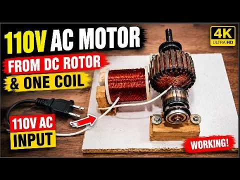
How to Build a DIY 110V AC Motor Using a DC Rotor and a Single Coil
Introduction: Understanding the DIY Motor Project
Building electric motors has always been one of the most fascinating areas of DIY engineering. Whether you are an electronics enthusiast, a student, or someone who enjoys experimenting with electrical machines, constructing a custom motor provides valuable insight into how electricity is converted into mechanical motion. In this project, a standard DC motor rotor is repurposed as the heart of a homemade 110V AC motor using only a single hand-wound copper coil. Rather than simply assembling components, this project demonstrates important concepts such as magnetic fields, electromagnetic induction, coil winding, rotor alignment, and electrical connections. It also shows how existing electrical components can be reused creatively to build educational prototypes.
The project begins by testing the original DC motor to verify that its rotor and magnetic assembly are still in good working condition. Instead of immediately disassembling the motor, the output is checked by manually rotating the shaft and observing the generated voltage. This simple procedure confirms whether the rotor can produce electricity through electromagnetic induction. Once the output reaches approximately 110 volts during manual testing, the rotor becomes an ideal candidate for the custom motor project. Performing this initial inspection helps avoid unnecessary work on damaged or faulty components and provides confidence before moving to the construction phase.
One of the most interesting aspects of this project is its simplicity. Unlike commercial AC motors that contain multiple stator windings, laminated steel cores, and complex manufacturing processes, this demonstration relies on only one carefully wound coil positioned next to a reused DC rotor. Although the design is educational rather than industrial, it effectively illustrates the interaction between magnetic fields and electrical current. Watching a homemade motor begin to rotate after careful assembly gives builders a much deeper understanding of motor principles than simply reading about them in textbooks.
Another important feature of this project is the use of inexpensive and easily available materials. The wooden mounting plate provides a stable framework while remaining easy to drill and modify. A plastic bobbin serves as the foundation for winding the copper wire, and ordinary enamel-coated magnet wire forms the electromagnetic coil. Since most of these materials can be found in workshops or purchased at low cost, the project is accessible to hobbyists around the world. Recycling components from old motors also reduces waste and encourages sustainable engineering practices.
Throughout the build, careful alignment and precision play a major role in the motor's performance. The rotor must remain perfectly centered on the shaft, the coil must be positioned accurately beside the rotating magnetic field, and every electrical connection must be secure before applying power. Small mechanical errors can increase friction, reduce efficiency, or prevent the motor from operating smoothly. Paying attention to these details teaches valuable engineering habits that apply to many other electrical and mechanical projects.
Above all, this project should be viewed as an educational experiment designed to demonstrate the principles of electricity and magnetism. It encourages curiosity, creative thinking, and hands-on learning while reminding builders to respect the hazards associated with electrical equipment. By combining simple materials with fundamental engineering concepts, this DIY motor project offers an enjoyable opportunity to explore how electric motors work from the inside out.
Testing the DC Motor Before Disassembly
Every successful engineering project begins with proper testing, and this motor build is no exception. Before taking the DC motor apart, its operating condition must be verified to ensure that the rotor and internal magnets are functioning correctly. Testing first prevents unnecessary assembly work using damaged components and establishes a reliable starting point for the project. Even experienced engineers routinely inspect electrical devices before modifying them because identifying problems early saves both time and materials.
The testing procedure is straightforward. A light bulb is connected across the motor's output terminals, and the motor shaft is rotated manually using a rope or similar method. As the rotor spins inside the permanent magnetic field, electrical energy is generated through electromagnetic induction. If the motor is healthy, the connected light bulb begins to glow, indicating that voltage is being produced. A multimeter can also be connected simultaneously to measure the generated voltage more accurately and monitor the electrical output during rotation.
In this demonstration, the manually rotated motor generates approximately 110 volts under test conditions. This result confirms that the rotor remains magnetically effective and capable of producing a significant electrical output. Although the exact voltage depends on rotational speed, magnetic strength, and winding characteristics, reaching the target voltage provides confidence that the rotor is suitable for the planned DIY AC motor project. This simple diagnostic step eliminates guesswork before construction begins.
Testing also provides valuable educational insight into generator operation. Many people are surprised to discover that electric motors and generators are fundamentally similar machines. When supplied with electricity, a motor converts electrical energy into mechanical rotation. Conversely, when the shaft is rotated externally, the same device produces electricity. Observing this dual functionality helps builders understand the close relationship between motors and generators and illustrates the principle of electromagnetic induction discovered by Michael Faraday.
Another benefit of testing before disassembly is identifying mechanical problems. During manual rotation, builders can listen for unusual noises, feel excessive bearing resistance, or detect vibration caused by damaged shafts. A smoothly rotating motor generally indicates healthy bearings and proper alignment, while rough movement may signal worn mechanical parts requiring repair or replacement. Addressing these issues before rebuilding significantly improves the final project's reliability.
After confirming the motor's electrical output and mechanical condition, the builder can proceed with confidence to the next stage. Knowing that the rotor is capable of generating approximately 110 volts provides a clear design goal for the rest of the project. This careful preparation demonstrates an important engineering principle: always verify component performance before incorporating it into a larger system.
Removing and Preparing the Rotor
With the initial testing completed successfully, attention turns to carefully disassembling the DC motor and extracting its rotor. This stage requires patience because the rotor is the most important component of the entire project. Any accidental damage during removal could affect magnetic balance, shaft alignment, or overall performance. Using appropriate hand tools and working methodically helps preserve every part for later assembly.
Once the motor housing is opened, the rotor is gently removed from the stator assembly. Builders should avoid forcing the shaft through the bearings, as excessive pressure can bend the shaft or damage bearing surfaces. If necessary, small bearing pullers or soft plastic tools can assist with disassembly while minimizing the risk of mechanical damage. Keeping all removed components organized also simplifies reassembly and future maintenance.
After removal, the rotor should be carefully inspected. Dust, rust, grease, or accumulated debris should be cleaned using appropriate cleaning materials that will not damage the insulation or magnetic surfaces. The shaft should be checked for straightness, while the commutator and magnetic sections should be examined for visible wear or damage. Cleaning the rotor improves appearance while reducing unnecessary friction during operation.
The next step involves mounting the rotor securely onto a sturdy wooden base. Wood is an excellent choice for experimental prototypes because it is inexpensive, easy to machine, and electrically insulating. A precisely drilled center hole ensures that the shaft remains perfectly aligned while rotating. If the rotor is mounted even slightly off-center, vibration can occur, leading to unstable operation and unnecessary mechanical stress.
Proper alignment cannot be overstated. The rotor should rotate freely without touching surrounding components, and the shaft should remain parallel to the base. Builders often rotate the assembly manually several times before proceeding to confirm that there is no wobble or binding. This careful inspection prevents problems that might otherwise appear later when electrical power is applied.
Preparing the rotor correctly establishes the mechanical foundation of the project. A well-balanced rotating assembly not only improves performance but also makes later adjustments much easier. Spending additional time during this preparation stage greatly increases the likelihood of achieving smooth and reliable motor operation during final testing.
Designing and Winding the Single Coil
The electromagnetic coil is the stationary component responsible for producing the magnetic field that interacts with the rotating rotor. Although the project uses only one coil, its construction requires careful attention to detail because winding quality directly affects the motor's electrical characteristics. Uniform winding produces a stronger and more consistent magnetic field, resulting in smoother operation.
Construction begins with a plastic bobbin that serves as the winding form. Plastic provides excellent electrical insulation while maintaining the coil's shape during assembly. Before winding starts, the beginning of the enamel-coated copper wire is secured firmly so that it does not slip while rotating. Careful preparation ensures an orderly winding process and reduces the likelihood of tangled wire.
The coil is wound using 0.573 mm enamel-coated copper wire. To speed up the process and maintain consistent tension, a drill machine rotates the bobbin while the wire is guided carefully by hand. Maintaining even spacing between each layer is important because uneven winding can create localized heating, irregular magnetic fields, and reduced efficiency. Patience during this step produces a neat, professional-looking coil.
The target winding count is approximately 350 turns. This number represents a balance between electrical resistance, magnetic field strength, and available space on the bobbin. As each layer is completed, the wire should remain tightly packed without crossing excessively or forming loose loops. Builders often pause periodically to check winding quality and ensure that the insulation remains undamaged throughout the process.
After reaching the required number of turns, the coil ends are secured to prevent the winding from loosening. The enamel insulation is carefully removed from the wire ends so they can later be connected electrically. Additional insulation tape or heat-resistant adhesive may be applied to improve durability and protect the winding during handling. Proper finishing contributes significantly to long-term reliability.
The completed coil demonstrates how a relatively simple component can perform an essential function in an electric motor. Although commercial motors often contain multiple coils and sophisticated winding patterns, this single-coil design effectively illustrates the basic principles of electromagnetic force. Building the coil by hand also provides valuable practical experience with one of the most fundamental components in electrical engineering.
Assembly, Electrical Connections, and Performance Testing
After both the rotor and coil have been prepared, the project moves into final assembly. The completed coil is positioned carefully beside the rotor on the wooden mounting plate, ensuring that the gap between the magnetic field and the rotating component remains consistent. Proper spacing allows the magnetic interaction to occur efficiently while preventing physical contact between moving and stationary parts. Alignment at this stage plays a critical role in achieving smooth motor operation.
Once the position has been verified, a strong adhesive is applied to secure the coil permanently to the wooden base. Allowing sufficient curing time is essential because any movement during operation could change the air gap or damage the winding. Builders should verify once again that the rotor spins freely before making any electrical connections. This final mechanical inspection helps eliminate problems before power is introduced.
Electrical wiring should always be completed carefully and methodically. According to the demonstrated setup, one wire from the coil is connected so it contacts the rotor as shown, while the remaining coil wire and the corresponding rotor wire are connected to the 110-volt AC supply. Every connection should be firmly attached and properly insulated to minimize the risk of loose contacts or electrical faults. Before energizing the circuit, it is wise to inspect each connection one final time and verify that all components are mounted securely.
When power is applied, the rotor begins rotating, demonstrating the interaction between the energized coil and the magnetic structure of the rotor. Watching the motor accelerate from a standstill is the highlight of the project because it confirms that the assembly has been completed correctly. The rotor continues spinning while the stationary coil remains fixed to the wooden base, illustrating the basic principle of converting electrical energy into mechanical motion through magnetic forces.
Although the demonstration successfully shows the motor operating, builders should remember that performance depends on several variables, including rotor balance, coil quality, magnetic strength, bearing condition, and supply characteristics. Small adjustments in alignment or winding quality can noticeably affect smoothness and efficiency. Experimenting with these variables provides an excellent learning opportunity for anyone interested in motor design and electromagnetic engineering.
Finally, safety must remain the highest priority throughout the project. Working with mains electricity presents serious risks, including electric shock, burns, and fire hazards. Always disconnect power before making adjustments, use insulated tools and appropriate protective equipment, and ensure that all exposed conductors are properly insulated. This project is intended solely for educational and experimental purposes, helping enthusiasts better understand motor construction while emphasizing responsible and safe engineering practices.
Conclusion
Building a DIY 110V AC motor using a recycled DC rotor and a single hand-wound coil is an engaging project that demonstrates the core principles of electromagnetism, motor construction, and hands-on engineering. Throughout the build, every stage—from testing the original DC motor, removing and preparing the rotor, winding a precise 350-turn coil with 0.573 mm copper wire, mounting the components on a wooden base, and making the final electrical connections—contributes to a deeper understanding of how electrical energy and magnetic fields work together to create motion. While the design is intended as an educational demonstration rather than a replacement for a commercial AC motor, it offers valuable practical experience that textbooks alone cannot provide.
One of the greatest benefits of this project is the opportunity to learn through experimentation. Builders can observe how small changes in coil alignment, winding quality, rotor balance, and electrical connections influence the motor's operation. These observations help develop troubleshooting skills and provide a stronger foundation for more advanced electrical and mechanical projects in the future. Reusing parts from an old DC motor also encourages creativity, reduces electronic waste, and shows how discarded components can become valuable learning tools.
Most importantly, safety should always come first when working with electricity. Always disconnect power before making adjustments, use properly insulated tools, wear appropriate protective equipment, and never work on energized circuits unless you have the necessary knowledge and experience. By following safe working practices and approaching each step carefully, you can enjoy exploring the fascinating world of DIY motor engineering while gaining practical knowledge that can be applied to many other electronics and engineering projects. Keep experimenting, continue learning, and let every project inspire your next engineering innovation.
Frequently Asked Questions (FAQs)
Everything you need to know about building a DIY 110V AC Motor using a DC Rotor and a Single Coil.
Yes. This project demonstrates an educational concept where a DC motor rotor is reused as part of a custom-built motor. It is intended for learning and experimentation.
Testing confirms that the rotor and magnets are working correctly before disassembling the motor, preventing unnecessary work.
This project uses approximately 0.573 mm enamel-coated copper magnet wire.
The demonstration uses approximately 350 turns on a plastic bobbin.
A plastic bobbin provides insulation, supports the winding, and helps maintain a neat coil shape.
Wood is inexpensive, easy to work with, electrically insulating, and provides a stable mounting platform.
Maintain constant wire tension and guide the wire evenly while rotating the bobbin.
Yes, but changing the wire size affects resistance, current capacity, and the total number of turns required.
Proper alignment reduces vibration, improves efficiency, and allows smooth rotation.
A fully cured adhesive prevents the coil from shifting during operation.
No. This project is intended for educational demonstrations and should not be used as a commercial AC motor replacement.
Basic tools include screwdrivers, pliers, a drill, soldering tools, glue, and a multimeter.
A digital multimeter is the safest and most accurate tool for measuring voltage.
A consistent air gap between the rotor and coil improves magnetic interaction and smooth operation.
In many cases, stronger magnets can produce a stronger magnetic field, but other design factors must also be considered.
Common causes include poor rotor balance, loose mounting, worn bearings, or incorrect alignment.
Yes, but beginners should understand basic electrical safety and work under proper supervision when necessary.
Disconnect power before adjustments, wear safety glasses, use insulated tools, and avoid exposed live wiring.
You will gain practical knowledge of electromagnetic induction, motor construction, mechanical alignment, and electrical assembly.
Absolutely. It is an excellent demonstration of fundamental electrical engineering concepts for students and hobbyists.
Discussion
No comments yet. Be the first to join the conversation!