
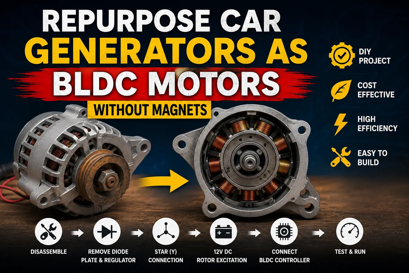
How to Convert a Car Generator into a BLDC Motor: Step-by-Step DIY Conversion Guide
Introduction to Converting a Car Generator into a BLDC Motor
Welcome to Multi Elector! In today's project, we are going to explore an exciting engineering experiment by converting a standard car generator, also known as an automotive alternator, into a Brushless DC (BLDC) motor. Many people think an alternator can only generate electricity for charging a vehicle's battery, but with a few modifications, it can also function as a three-phase electric motor. This project is designed for educational purposes and provides an excellent opportunity to understand how electromagnetic machines work. Whether you are a DIY enthusiast, an electrical engineering student, or someone who enjoys learning about electric motors, this guide will help you understand each step in detail.
Before we begin the conversion process, it is important to understand the basic difference between a generator and a motor. A generator converts mechanical energy into electrical energy. In a vehicle, the engine rotates the alternator, which produces alternating current (AC). This AC power is then converted into direct current (DC) by a diode rectifier so it can charge the vehicle's battery and power electrical accessories. A motor performs the opposite function. Instead of producing electricity, it receives electrical energy and converts it into mechanical rotation. Interestingly, both machines are based on the same principle of electromagnetic induction, which means that with the proper modifications, an alternator can be operated as a motor.
A BLDC motor operates using three-phase electrical signals supplied by a BLDC controller. Unlike traditional brushed motors, BLDC motors do not rely on carbon brushes to switch current between windings. Instead, the electronic controller energizes the stator windings in a precise sequence, creating a rotating magnetic field that causes the rotor to spin smoothly. Automotive alternators already contain three-phase stator windings, making them an excellent candidate for this educational conversion project. However, some components designed specifically for power generation, such as the diode rectifier and voltage regulator, must be removed because they are not required during motor operation.
Throughout this guide, we will carefully explain every stage of the conversion. We will start by opening the alternator and identifying its major components. Next, we will remove the diode plate and voltage regulator, prepare the rotor excitation wiring, identify the three stator phases, create a proper star connection, and finally connect the alternator to a BLDC motor controller for testing. Every step will be explained in simple language so that beginners can follow along while still providing enough technical detail for experienced electronics hobbyists.
Safety should always be your first priority when working with electrical equipment and rotating machinery. Before disassembling the alternator, disconnect every power source and wear appropriate safety equipment, including safety glasses and insulated gloves. Keep your workbench clean and organized, label every wire before disconnecting it, and take photographs during disassembly if necessary. These small precautions will make the reassembly process much easier and help prevent wiring mistakes. By the end of this project, you will have a much deeper understanding of three-phase electrical systems, electromagnetic fields, and the fascinating relationship between generators and electric motors.
Opening the Car Generator and Understanding Its Internal Parts
The first step in converting a car generator into a BLDC motor is carefully opening the alternator and becoming familiar with every component inside it. Many beginners rush directly into removing wires and cutting connections, but understanding how the alternator is constructed will make the entire conversion much easier and reduce the chance of damaging important parts. Every component inside the alternator has a specific purpose during electricity generation, and knowing what each part does helps you decide which components should remain and which ones can be removed during the modification process.
Before beginning, place the alternator on a clean workbench with plenty of lighting. Dirt, grease, and oil often accumulate on old automotive alternators, so it is a good idea to clean the outside first using a brush and a cloth. Cleaning the exterior prevents dust and debris from entering the bearings and windings once the housing is opened. Gather the necessary tools before starting the disassembly. A socket wrench set, Phillips and flat-head screwdrivers, Allen keys, needle-nose pliers, a marker, small storage containers for screws, and a digital camera or smartphone for taking reference photos are all helpful. Organizing your tools before beginning saves time and prevents misplaced hardware later during reassembly.
Most automotive alternators are held together by four long bolts that extend from the rear housing to the front housing. Carefully remove these bolts while supporting the alternator with one hand. Once the bolts are removed, gently separate the aluminum front and rear covers. Sometimes the housings may stick together due to corrosion or years of use. Instead of forcing them apart with excessive pressure, lightly tap the housing with a rubber mallet to loosen the fit. Avoid using steel hammers because they can crack or deform the aluminum casing. As the two halves separate, be careful not to damage the rotor shaft or bearings, since these parts are essential for smooth motor operation after the conversion.
With the alternator open, you can now identify its major components. At the center is the rotor, which contains an electromagnetic field winding wrapped around an iron core. Unlike many BLDC motors that use permanent magnets, most automotive alternators use an electromagnet that receives DC current through two slip rings mounted on the rotor shaft. Carbon brushes press against these slip rings, allowing electrical current to reach the rotating field winding. When current flows through the rotor winding, it produces a strong magnetic field that rotates with the shaft.
Surrounding the rotor is the stator, which remains stationary during operation. The stator consists of laminated steel cores with heavy copper windings arranged into three separate phases. These three-phase windings are the heart of both the generator and the future BLDC motor. During normal alternator operation, the rotating magnetic field produced by the rotor cuts across the stator windings and generates three-phase alternating current. During the conversion, these same windings will instead receive three-phase power from a BLDC controller to create a rotating magnetic field that drives the rotor.
At the rear of the alternator, you will also find the diode rectifier assembly, often called the diode plate. This component converts the three-phase AC generated by the stator into DC electricity for charging the vehicle battery. Attached nearby is the voltage regulator, which automatically adjusts the rotor current to maintain a constant charging voltage regardless of engine speed. Since a BLDC controller performs an entirely different function, both the rectifier and voltage regulator will eventually be removed during the conversion process.
Take a close look at the brush holder assembly as well. The carbon brushes should move freely inside their holders and maintain firm contact with the slip rings. If the brushes are excessively worn, cracked, or stuck due to dirt, consider replacing them before continuing. Good electrical contact between the brushes and slip rings is important because the rotor will still require DC excitation current after the conversion. Also inspect the slip rings for deep grooves or burn marks. Light polishing with fine sandpaper can improve electrical contact if necessary.
The bearings deserve careful attention because they determine how smoothly the converted motor will operate. Rotate the rotor by hand while it remains installed in the housing. It should spin freely with very little resistance and without grinding noises. If you hear rough sounds or feel excessive play in the shaft, replace the bearings before completing the project. Worn bearings increase friction, create vibration, reduce efficiency, and may eventually damage the stator windings if the rotor begins to rub against them.
Before removing any electrical connections, use a permanent marker or small adhesive labels to identify each stator wire. Taking several high-quality photographs from different angles is also highly recommended. These reference images become extremely valuable if you later need to verify the original wiring arrangement. Many experienced technicians rely on photographs during complex repairs because they eliminate uncertainty during reassembly.
Spend a few minutes studying how the components interact with each other. Notice how the rotor sits precisely in the center of the stator with only a small air gap separating them. This narrow gap allows the magnetic field to transfer energy efficiently while preventing physical contact during rotation. Understanding this relationship will help you appreciate why accurate assembly and proper bearing alignment are so important when converting the alternator into a BLDC motor.
Now that the alternator has been fully opened and every major component has been identified, you are ready to begin the actual modification process. In the next section, we will remove the diode plate, voltage regulator, and unnecessary charging electronics, preparing the stator for its new role as the three-phase winding of a BLDC motor.
Removing the Diode Plate and Preparing the Alternator for BLDC Conversion
Now that we have opened the car generator and identified all of its major components, the next step is to remove the electrical parts that are only required for charging a vehicle's battery. A standard automotive alternator is designed to generate three-phase alternating current (AC), which is then converted into direct current (DC) by the diode rectifier. Since we are converting the alternator into a BLDC motor, this conversion process is no longer needed. Instead of generating electricity, the stator windings will receive three-phase current directly from a BLDC controller. This means several factory-installed electronic components can be safely removed.
Before touching any wiring, carefully inspect the rear section of the alternator. You will notice the diode rectifier assembly, commonly called the diode plate, mounted inside the rear housing. This component is usually made of aluminum and contains several high-current diodes pressed into large heat sinks. The stator windings are connected directly to this plate because the alternator produces three separate AC outputs. The diodes combine these three phases and convert them into a stable DC output suitable for charging a 12-volt battery.
Take a few photographs of the wiring before disconnecting anything. Even though many of these parts will not be reused, having reference images is always helpful if you need to compare the original wiring arrangement later. Use a marker or small labels to identify the three stator winding leads before removing them from the diode plate. This simple step can save a significant amount of time when reconnecting the windings during the star configuration later in the project.
Using a soldering iron or the appropriate hand tools, carefully disconnect the stator wires from the diode plate. Work slowly and avoid applying excessive force because the copper winding wires are coated with insulation that can easily be damaged. If solder is present, heat each joint only long enough to melt the solder before gently lifting the wire away. If mechanical fasteners are used instead, loosen them carefully without twisting the copper conductors.
After all three stator leads have been disconnected, remove the screws or mounting bolts holding the diode plate inside the housing. Lift the assembly out slowly while checking that no wires remain attached. Once removed, examine the diode plate closely. You will notice several large power diodes arranged to form a full-wave three-phase rectifier bridge. These components are essential for electricity generation but serve no useful purpose when the alternator is operated as a motor using an external BLDC controller.
Set the diode plate aside in a safe place. Even though it will not be reused in this project, it remains a valuable electronic component that can be recycled or used in future power supply projects. Never throw electronic parts into ordinary household waste. Many recycling centers accept electronic components and recover valuable metals from them.
Next, locate the voltage regulator. This small electronic module is usually mounted near the brush holder assembly. During normal vehicle operation, the voltage regulator continuously monitors the alternator output and adjusts the current flowing through the rotor field winding. This automatic regulation keeps the charging voltage stable regardless of engine speed or electrical load. Since the BLDC controller will control motor operation instead, the original voltage regulator is no longer required.
Remove the screws securing the voltage regulator and disconnect its electrical connector if one is present. Lift the regulator away carefully without damaging the nearby brush holder. Some alternators combine the regulator and brush holder into one assembly, while others use separate components. If your alternator has an integrated design, pay close attention to how the carbon brushes remain positioned against the slip rings because we still need these brushes to supply DC excitation to the rotor winding later in the conversion.
After removing the regulator, inspect the brush holder assembly. Press each carbon brush gently with your finger to ensure it moves freely inside its guide. The spring should push the brush smoothly back into contact with the slip ring. If a brush sticks due to dirt, corrosion, or excessive wear, clean the holder carefully using electrical contact cleaner. Replace any cracked or heavily worn brushes because reliable electrical contact is essential for maintaining the rotor's magnetic field during motor operation.
Now examine the slip rings on the rotor shaft. These two smooth copper rings transfer current from the stationary brushes to the rotating field winding. Over time, the rings may develop grooves, oxidation, or carbon deposits from brush wear. If necessary, polish them lightly using very fine sandpaper or a polishing cloth. Avoid removing too much material because the slip rings must remain perfectly round for smooth brush contact. After polishing, wipe away all dust with a clean cloth or compressed air.
With the rectifier and regulator removed, the stator windings become much easier to inspect. Look carefully at every winding for signs of overheating, burned insulation, broken wires, or loose connections. A healthy stator should have clean copper windings with intact insulation. Slight discoloration from age is normal, but blackened insulation or a burnt smell may indicate previous overheating. If serious damage is present, repair or rewind the stator before continuing with the conversion.
This is also a good opportunity to clean the inside of the alternator thoroughly. Years of operation often leave dust from carbon brushes, oil residue, and road debris inside the housing. Use compressed air, a soft brush, or electrical contact cleaner to remove contamination. A clean stator improves cooling, makes wire identification easier, and reduces the chance of electrical shorts after reassembly.
Once cleaning is complete, use a digital multimeter to check the continuity of each stator winding. Measure the resistance between the ends of each phase winding. The readings should be nearly identical because all three phases are wound with similar lengths of copper wire. If one phase shows significantly higher or lower resistance than the others, inspect it carefully for loose connections or damaged windings before moving forward.
Finally, organize the three stator phase wires so they are clearly separated and easy to identify. These wires will soon be connected into a star (Y) configuration, which is one of the most important steps in converting the alternator into a functional BLDC motor. Correct identification of these three phases ensures smooth motor operation, balanced current flow, and proper communication with the BLDC controller.
At this stage, the alternator has been stripped of all unnecessary charging electronics. The diode plate, voltage regulator, and related components have been removed, while the rotor, stator, bearings, brushes, and slip rings remain intact. The alternator is now ready for the next phase of the project, where we will prepare the rotor excitation wiring and provide a dedicated 12-volt DC supply to create the magnetic field needed for BLDC motor operation.
Preparing the Carbon Brush Wires for a 12-Volt Rotor Excitation Supply
After removing the diode plate and voltage regulator, the alternator is much closer to becoming a functional BLDC motor. However, one very important component still needs attention—the rotor. Unlike most modern BLDC motors that use permanent magnets, a standard automotive alternator uses an electromagnetic rotor. This means the rotor must receive a continuous DC power supply to create the magnetic field required for operation. Without this magnetic field, the stator cannot produce the torque needed to rotate the shaft, regardless of how powerful the BLDC controller may be.
The rotor is located at the center of the alternator and rotates inside the stationary stator windings. It consists of a copper field winding wrapped around an iron core, enclosed by two claw-shaped pole pieces. When DC current flows through this field winding, it produces north and south magnetic poles around the rotor. These poles interact with the rotating magnetic field generated by the stator windings, causing the rotor to spin. This magnetic interaction is the foundation of both generators and electric motors.
Originally, the rotor received its excitation current through the alternator's voltage regulator. The regulator controlled the amount of current flowing through the carbon brushes and slip rings, automatically adjusting the magnetic field strength depending on engine speed and battery voltage. Since the voltage regulator has now been removed, we must create a new method of supplying DC power directly to the rotor.
Begin by locating the two carbon brushes inside the brush holder assembly. These brushes press against the two copper slip rings mounted on the rotor shaft. Their purpose is to transfer electrical current from the stationary housing to the rotating field winding. Carefully inspect both brushes before proceeding. They should move freely inside their holders and be pushed firmly against the slip rings by their springs. If either brush is worn down to only a few millimeters in length, replace it with a new one. Worn brushes reduce electrical contact and can cause unstable motor performance.
Next, inspect the slip rings themselves. They should have a smooth, shiny copper surface. If they appear dark, oxidized, or heavily grooved from years of brush wear, polish them gently using very fine sandpaper such as 1000-grit or a polishing pad designed for electrical contacts. Rotate the rotor by hand while polishing to maintain an even surface. After polishing, clean away all copper dust using compressed air or electrical contact cleaner. Good electrical contact between the brushes and slip rings is essential because the rotor depends entirely on this connection for its magnetic field.
Now prepare two insulated wires that will carry approximately 12 volts DC to the rotor winding. Choose flexible, heat-resistant wire with an appropriate current rating, typically between 16 AWG and 18 AWG depending on the size of the alternator. Strip a small amount of insulation from each end and solder one wire to each carbon brush terminal. If the brush holder uses screw terminals instead of soldered connections, tighten the wires securely while ensuring they cannot loosen due to vibration.
Route these two wires carefully through the alternator housing. Make sure they do not interfere with the rotating fan, pulley, or rotor shaft. Use rubber grommets where the wires pass through metal openings to prevent insulation damage. Secure the wiring with cable ties so it remains fixed during operation. Loose wires inside a rotating machine can quickly become damaged and may cause electrical shorts or mechanical failure.
Before applying power, it is important to verify that the rotor winding is electrically healthy. Using a digital multimeter, measure the resistance across the two slip rings. Most automotive alternators have a rotor resistance between 2 and 6 ohms, although the exact value depends on the alternator model. A reading within this range usually indicates that the field winding is intact. If the meter shows infinite resistance, the rotor winding is open and will need repair. If the resistance is extremely low, there may be an internal short circuit that could cause excessive current draw.
Another useful test is checking for continuity between either slip ring and the rotor shaft. Place one multimeter probe on a slip ring and the other on the metal shaft. The meter should show no continuity, indicating that the field winding is properly insulated from the rotor core. If continuity exists, the insulation has failed, and the rotor should be repaired or replaced before continuing.
Once the electrical tests are complete, connect the two excitation wires to a regulated 12-volt DC power supply. It is recommended to include a small fuse, typically between 3 and 5 amps, in series with the positive wire. This fuse protects the rotor winding against accidental short circuits during testing. You may also install a simple on/off switch so the field current can be controlled independently of the BLDC controller.
When power is first applied to the rotor, the field winding becomes energized and produces a strong magnetic field. Although the rotor will not rotate by itself, you may notice a slight magnetic attraction if you bring a steel screwdriver close to the claw poles. This is a quick way to confirm that the excitation circuit is functioning correctly. Avoid leaving the rotor energized for long periods without ventilation, as the winding can gradually heat up if current flows continuously.
At this stage, the alternator now has an independent DC excitation system for its rotor. This magnetic field will remain constant while the BLDC controller energizes the stator windings in sequence. The combination of a stationary magnetic field in the rotor and a rotating magnetic field in the stator allows the converted alternator to operate similarly to a brushless DC motor.
Before moving to the next stage, inspect your work one final time. Confirm that the brush wires are securely connected, the slip rings are clean, the fuse is installed, and no wires can touch any rotating parts. A careful inspection now can prevent unnecessary troubleshooting later.
With the rotor excitation system completed, the alternator is almost ready to operate as a BLDC motor. The next and perhaps most important step is identifying the three stator windings and connecting them into a star (Y) configuration, which provides balanced three-phase operation and allows the BLDC controller to drive the motor efficiently.
Connecting the Three Stator Windings in a Star (Y) Configuration
Now that the rotor excitation system is complete, the next major step is preparing the stator windings for operation with a BLDC controller. This is one of the most important stages of the entire conversion because the quality of the winding connections directly affects the motor's performance, efficiency, smoothness, and reliability. A mistake during this step can cause poor starting torque, excessive current draw, overheating, or even damage the BLDC controller. Therefore, work slowly, double-check every connection, and use a digital multimeter frequently to verify your results.
The stator is the stationary part of the alternator that surrounds the rotor. It contains three separate copper windings, commonly referred to as Phase A, Phase B, and Phase C. During normal alternator operation, these three windings generate three-phase alternating current as the rotor's magnetic field rotates inside them. After the conversion, these same windings will receive three-phase electrical pulses from the BLDC controller. Instead of producing electricity, they will create a rotating magnetic field that causes the rotor to spin.
Before making any new connections, identify the beginning and end of each winding. Depending on the alternator model, the winding ends may already be visible after removing the diode plate. In some alternators, however, the winding junctions are covered with insulation, varnish, or protective sleeves. Carefully remove any insulation only where necessary, taking care not to damage the enamel coating on the copper wire.
A digital multimeter is the most useful tool during this stage. Set the meter to the continuity or low-resistance mode. Touch one probe to a wire and use the second probe to test the remaining wires until continuity is found. When continuity exists, both wires belong to the same winding. Label these wires clearly as A1 and A2. Repeat the process for the remaining two windings, marking them as B1 and B2, and C1 and C2. Taking time to label the wires now will greatly simplify the rest of the wiring process.
Once all three windings have been identified, inspect each wire carefully. Look for damaged insulation, broken strands, loose solder joints, or signs of overheating. If the copper appears blackened or brittle, repair the damage before continuing. Healthy windings should have clean insulation and nearly identical resistance measurements. Measure the resistance of each phase using the multimeter. All three windings should have very similar values. Small differences are acceptable, but large variations may indicate a damaged winding that should be repaired before the motor is assembled.
For this project, we will use a Star (Y) connection, which is commonly used in many industrial three-phase motors. In a star connection, one end of each winding is connected together to form a common neutral point. The remaining three wire ends become the three motor phase terminals that connect directly to the BLDC controller.
To create the star connection, join A2, B2, and C2 together. Twist the wires securely, solder the connection thoroughly, and cover it with heat-shrink tubing or several layers of high-quality electrical insulation. This common junction should remain completely insulated because it is not normally connected to the controller. The remaining wires—A1, B1, and C1—become the three motor outputs that will later connect to the controller terminals labeled U, V, and W.
When soldering the winding connections, use a sufficiently powerful soldering iron so the joint heats evenly without overheating the insulation. Apply fresh solder until it flows smoothly around the copper conductors, creating a shiny, solid connection. Avoid cold solder joints, which often appear dull or rough and may create high electrical resistance. After soldering, gently pull each wire to verify that the joint is mechanically secure before insulating it.
Heat-shrink tubing is highly recommended because it provides better protection than ordinary electrical tape. Slide the tubing over the joint before soldering, then move it into position afterward and shrink it evenly using a heat gun. If heat-shrink tubing is unavailable, wrap the connection carefully with multiple layers of high-quality electrical tape, ensuring that no bare copper remains exposed.
After completing the star connection, perform another series of electrical tests. Measure the resistance between each pair of output wires: A1 to B1, B1 to C1, and C1 to A1. The readings should all be nearly identical. Equal resistance confirms that the windings are balanced and correctly connected. If one reading differs significantly from the others, inspect the wiring carefully for loose connections or incorrect phase identification.
Next, check for insulation faults. Place one multimeter probe on the alternator housing and the other on each phase wire individually. There should be no continuity between any phase wire and the metal housing. If continuity exists, a winding may be shorted to the stator core, which must be repaired before operating the motor.
Now organize the three output wires neatly. Route them through the original wiring opening or create a protected exit point using a rubber grommet. Leave enough wire length to comfortably connect the BLDC controller while preventing the wires from contacting the rotating fan or pulley. Secure them inside the housing using cable ties so vibration cannot damage the insulation during operation.
At this stage, it is useful to understand why a star connection is preferred for this conversion. Compared to a delta connection, a star configuration generally provides smoother startup characteristics, lower starting current, and better low-speed torque. These advantages make it especially suitable for educational BLDC conversions, where stable operation is more important than maximum speed. The star connection also distributes current evenly across the three windings, helping reduce heating and improving overall reliability.
Before closing the alternator housing, inspect every connection one final time. Confirm that the neutral junction is fully insulated, all three phase wires are securely attached, no solder joints are loose, and every wire is properly routed away from moving components. Rotate the rotor by hand to ensure nothing rubs against the stator or wiring. The shaft should turn smoothly without resistance other than the normal bearing friction.
With the stator now rewired into a balanced three-phase star configuration, the alternator has completed its most significant electrical modification. The machine is no longer configured as a battery-charging generator but is now electrically prepared to operate as a three-phase brushless motor. In the next section, we will connect a BLDC controller, apply power safely, perform the first motor test, and troubleshoot any issues that may arise during startup.
The BEST Way to Repurpose Car Generators as BLDC Motors Without Magnets
Conclusion
Congratulations! You have successfully completed the process of converting a car generator (automotive alternator) into a brushless DC (BLDC) motor. Throughout this project, we carefully disassembled the alternator, identified its internal components, removed the diode rectifier and voltage regulator, prepared the rotor for a separate 12-volt DC excitation supply, rewired the stator into a three-phase star (Y) configuration, and prepared the motor for operation with a BLDC controller. Each step demonstrated the fascinating relationship between generators and motors, showing that both machines operate using the same fundamental principles of electromagnetism.
This conversion is an excellent educational project for electronics enthusiasts, engineering students, and DIY hobbyists who want to gain hands-on experience with three-phase electrical machines. While a converted alternator may not deliver the same performance as a purpose-built BLDC motor, it provides valuable insight into motor construction, magnetic fields, stator windings, rotor excitation, and electronic motor control. Understanding these concepts builds a strong foundation for more advanced projects involving electric vehicles, renewable energy systems, industrial automation, and custom motor design.
Before using your converted motor for any experiment, always perform thorough electrical and mechanical inspections. Check that all wiring connections are secure, ensure the rotor spins freely, verify equal resistance across all three stator phases, and confirm that no wires are touching the rotating components. During the first test, begin with a low-voltage power supply and monitor current, temperature, and vibration. If the motor rotates in the wrong direction, simply interchange any two of the three phase wires connected to the BLDC controller.
Always remember that safety comes first. Use insulated tools, wear eye protection, keep hands away from rotating parts, and never exceed the voltage or current ratings of your controller and power supply. Proper mounting and ventilation are also important to prevent vibration and overheating during extended operation.
Thank you for following this Multi Elector tutorial. I hope this project has helped you better understand how automotive alternators work and how they can be creatively modified for educational purposes. If you enjoyed this guide, don't forget to like the video, share it with your friends, and subscribe to Multi Elector for more DIY electrical engineering projects, motor conversions, generator experiments, and practical electronics tutorials. Keep learning, keep experimenting, and I'll see you in the next project.
Frequently Asked Questions (FAQs)
| Question | Answer |
|---|---|
| 1. Can a car generator really be converted into a BLDC motor? | Yes. With proper rewiring, removal of the rectifier, and a suitable BLDC controller, an automotive alternator can be operated as an educational BLDC motor. |
| 2. Why is the diode plate removed? | The diode plate converts AC into DC for battery charging. A BLDC controller already provides three-phase output, so the rectifier is unnecessary. |
| 3. Is the voltage regulator required? | No. The original voltage regulator is only used during charging mode and is not needed for BLDC motor operation. |
| 4. Why does the rotor need a 12V DC supply? | The alternator rotor uses an electromagnet instead of permanent magnets, so it requires DC excitation to create its magnetic field. |
| 5. Can I use a normal DC motor controller? | No. You should use a three-phase BLDC controller designed to drive brushless motors. |
| 6. What is a star (Y) connection? | A star connection joins one end of all three stator windings together while the remaining three ends connect to the BLDC controller. |
| 7. Can I use a delta connection instead? | Yes, but a star connection usually provides smoother startup, lower current, and better low-speed torque for this type of project. |
| 8. How do I reverse the motor direction? | Swap any two of the three phase wires connected between the stator and the BLDC controller. |
| 9. Do I need Hall sensors? | Not always. Many modern sensorless BLDC controllers can operate this conversion successfully. |
| 10. Can this converted motor power an electric vehicle? | Generally no. This project is intended for learning and experimentation rather than high-performance applications. |
| 11. What tools are required? | You need screwdrivers, socket wrenches, pliers, a soldering iron, multimeter, wire cutters, heat shrink tubing, and insulated wiring. |
| 12. Why should I measure winding resistance? | Equal resistance confirms that all three stator phases are healthy and properly connected. |
| 13. What happens if one phase is wired incorrectly? | The motor may vibrate, fail to start, overheat, or damage the BLDC controller. |
| 14. Is this project safe for beginners? | Yes, provided proper electrical safety procedures are followed and testing is performed using a low-voltage power supply. |
| 15. What is the biggest benefit of this conversion? | It helps you understand how alternators, BLDC motors, electromagnetic fields, and three-phase electrical systems work in real engineering applications. |
Discussion
No comments yet. Be the first to join the conversation!