
How to Convert a 220V Ceiling Fan Motor into a DIY BLDC Motor: Complete Step-by-Step Guide
Introduction
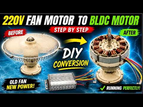
Have you ever looked at an old ceiling fan motor and wondered whether it could be transformed into something more advanced and efficient? Many DIY enthusiasts and electrical hobbyists enjoy experimenting with motors, generators, and renewable energy projects. One of the most interesting modifications you can perform is converting a standard 220V ceiling fan motor into a Brushless DC (BLDC) motor.
BLDC motors are widely used in modern technology because they offer excellent efficiency, smooth operation, reduced maintenance, and precise speed control. They can be found in electric vehicles, drones, cooling fans, power tools, and industrial machinery. While commercial BLDC motors are readily available, converting an existing AC fan motor into a BLDC motor is an exciting educational project that helps you understand motor construction, winding techniques, magnetic fields, and electronic motor control systems.
In this guide, we will walk through the complete process of converting a traditional ceiling fan motor into a DIY BLDC motor. From disassembly and winding removal to rewinding, magnet installation, electrical connections, and final testing, every stage plays an important role in achieving a successful conversion.
Disassembling the Fan Motor and Removing the Original Windings
The first step in any motor conversion project is carefully opening the motor and inspecting its internal components. Before beginning any work, it is important to disconnect the motor from any power source and prepare a clean workspace where small parts can be safely organized.
The motor is disassembled by removing the front and rear covers, allowing access to the stator and rotor assembly. Once opened, the original factory-installed copper windings become visible. These windings were specifically designed for AC operation and are not suitable for BLDC motor functionality.
Because the goal of this project is to create a brushless DC motor, all original winding wires must be completely removed. This process requires patience and attention to detail because the stator core must remain undamaged. The copper wire is carefully disconnected and extracted from the stator slots while preserving the integrity of the laminated steel core.
After the winding removal process is complete, the stator slots are thoroughly cleaned. Any remaining insulation paper, dust, adhesive residue, or debris should be removed. A clean stator provides a solid foundation for the new winding configuration and helps improve the overall reliability of the motor.
Taking extra time during this preparation stage is important because any damage or contamination can negatively affect the rewinding process and final motor performance.
Planning the BLDC Winding Layout and Preparing the Stator
Once the stator has been cleaned and inspected, preparation for the new BLDC winding can begin. The first task is installing insulation paper inside every stator slot. This insulating material prevents the copper wire from making direct contact with the metal stator core, reducing the risk of short circuits and electrical failures.
Proper winding design is one of the most critical aspects of a successful BLDC motor conversion. Before any wire is installed, the stator slot arrangement must be carefully analyzed. In this project, the motor contains a total of sixteen stator slots.
A challenge arises because sixteen slots cannot be evenly divided into three equal phases. To solve this problem, four slots are intentionally left unused. This leaves twelve active slots that can be divided equally into three groups of four slots each.
Each group represents one phase of the three-phase BLDC motor. This arrangement creates a balanced magnetic field distribution and simplifies the winding process. Careful planning at this stage ensures that the motor will operate smoothly once connected to a BLDC controller.
Marking the slots before winding begins is highly recommended. This helps prevent mistakes during coil installation and ensures that each phase is positioned correctly according to the winding diagram. Even small errors in slot assignment can significantly impact motor performance, efficiency, and startup characteristics.
A well-planned winding layout forms the foundation of the entire conversion project and directly influences the success of the finished motor.
Winding and Installing the Three-Phase Coils
With the stator prepared and the slot arrangement finalized, the actual winding process can begin. For this project, 0.87 mm diameter copper wire is used to create the coils.
The motor requires three identical coils to form the three phases of the BLDC motor. Consistency is extremely important during winding because any variation between coils can create imbalance and reduce performance. Each coil is wound with exactly twenty-eight turns of copper wire to maintain equal electrical characteristics across all three phases.
After the coils are completed, they are carefully inserted into their designated stator slots. Installing the coils requires patience because the wire insulation must remain intact throughout the process. Damaged insulation can lead to short circuits and motor failure.
The first coil is positioned according to the winding plan, followed by the second and third coils. During installation, three slots are left between the input wires in each section. This spacing is an important part of the design and contributes to the magnetic field pattern necessary for proper BLDC motor operation.
As each coil is inserted, the wires are neatly arranged within the stator slots to prevent unnecessary overlap and mechanical stress. Proper wire placement improves heat dissipation, simplifies final assembly, and enhances long-term reliability.
After all three coils have been installed, the stator begins to resemble a true three-phase BLDC motor. The completed winding layout clearly shows the separate phase groups and demonstrates the transformation from the original AC motor design into a brushless motor configuration.
Electrical Connections, Rotor Magnets, and Motor Assembly
After installing all three winding circuits, the next stage involves making the electrical connections. Each coil has two wire ends, and these wires must be connected according to the selected winding configuration.
One wire from each of the three winding circuits is connected together to form a common junction point. This creates the shared connection used in the motor's three-phase winding arrangement. The remaining wire from each phase remains separate and serves as the output connection that will later connect to the BLDC motor controller.
Before proceeding further, every connection should be carefully inspected. Loose joints, incorrect wiring, or poor solder connections can prevent the motor from operating correctly and may damage the controller.
Once the electrical connections have been completed, the stator core is reinstalled inside the motor housing. Care must be taken to ensure that the winding wires are properly routed and protected from being pinched during assembly.
The rotor plays an equally important role in BLDC motor operation. Instead of relying on traditional AC induction principles, the rotor uses permanent magnets to create the magnetic field required for brushless operation. In this project, four permanent magnets are installed and aligned within the rotor assembly.
Correct magnet placement is essential because the magnetic field generated by the rotor must interact efficiently with the stator windings. Proper magnet alignment helps maximize torque production, improve efficiency, and ensure smooth motor rotation.
After installing the rotor, the front and rear motor covers are secured in place, and all mounting screws are tightened. At this stage, the mechanical assembly of the BLDC motor conversion is complete.
Testing the Converted BLDC Motor and Final Results
The most exciting stage of the entire project is the first operational test. After hours of planning, winding, wiring, and assembly, it is finally time to determine whether the conversion has been successful.
The three phase output wires from the stator winding are connected to the corresponding terminals of a BLDC motor controller. Before applying power, every connection is checked one final time to ensure proper wiring and safe operation.
Once the controller receives power, the motor can be started gradually. If the winding arrangement and electrical connections have been completed correctly, the rotor should begin rotating smoothly.
During testing, the converted motor demonstrates successful operation. The controller sends sequential signals to the three winding phases, creating a rotating magnetic field that interacts with the permanent magnets in the rotor. This interaction causes continuous rotation, just like a commercial BLDC motor.
Seeing the motor run successfully is one of the most rewarding moments of the entire project. It confirms that the winding design, magnet placement, electrical connections, and assembly procedures were all completed correctly.
Beyond the technical achievement, this project provides valuable insight into motor design and operation. It demonstrates how traditional electrical machines can be modified and repurposed using creativity, engineering knowledge, and hands-on experimentation.
Conclusion
Converting a 220V ceiling fan motor into a DIY BLDC motor is an educational and rewarding engineering project. The process involves disassembling the motor, removing the original windings, preparing the stator, creating a balanced three-phase winding system, installing permanent magnets, making electrical connections, and testing the finished motor with a BLDC controller.
While this project requires patience and careful attention to detail, it offers an excellent opportunity to learn about motor construction, electromagnetic principles, and brushless motor technology. Whether you are a hobbyist, student, maker, or electronics enthusiast, projects like this help build practical skills and deepen your understanding of electrical engineering.
Always remember to follow proper safety procedures when working with electrical equipment and rotating machinery. With the right tools, planning, and determination, even an ordinary ceiling fan motor can be transformed into a functional and impressive DIY BLDC motor.
Frequently Asked Questions About Converting a 220V Fan Motor into a BLDC Motor
| Question | Answer |
|---|---|
| What is a BLDC motor? | A BLDC (Brushless DC) motor is an electric motor that uses electronic commutation instead of brushes, providing higher efficiency and longer lifespan. |
| Can a 220V ceiling fan motor be converted into a BLDC motor? | Yes, with proper rewinding, magnet installation, and a BLDC controller, many fan motors can be converted successfully. |
| Why convert a fan motor into a BLDC motor? | BLDC motors offer better efficiency, smoother operation, reduced maintenance, and improved speed control. |
| What tools are required for this conversion? | Basic tools include screwdrivers, pliers, wire cutters, soldering equipment, insulation paper, and a multimeter. |
| Why are the original windings removed? | The original AC windings are not suitable for BLDC operation and must be replaced with a three-phase winding configuration. |
| How many stator slots are used in this project? | Out of 16 slots, 12 are used for winding while 4 slots are left unused to create a balanced three-phase system. |
| What wire size is used for the new winding? | This project uses 0.87 mm diameter copper wire for creating the stator coils. |
| How many turns are wound in each coil? | Each coil contains 28 turns to maintain balanced electrical characteristics across all phases. |
| How many phases does the converted motor have? | The converted motor operates as a three-phase BLDC motor. |
| Why is insulation paper important? | Insulation paper prevents the copper wire from touching the stator core and causing short circuits. |
| How are the winding circuits connected? | One end of each phase is connected together, while the remaining three wires are connected to the BLDC controller. |
| What type of magnets are used in the rotor? | Four permanent magnets are installed in the rotor to generate the magnetic field required for BLDC operation. |
| Why is magnet alignment important? | Proper magnet alignment ensures smooth rotation, maximum efficiency, and reliable motor performance. |
| Can the converted motor run directly on AC power? | No. The motor requires a BLDC controller and DC power source for operation. |
| What controller is needed for this motor? | A compatible three-phase BLDC motor controller is required to drive the motor. |
| How do I test the converted motor? | Connect the three phase wires to the controller, verify all wiring, and gradually apply power to test operation. |
| What are the common mistakes during conversion? | Incorrect winding patterns, loose connections, damaged insulation, and poor magnet alignment are common mistakes. |
| Is this project suitable for beginners? | It is best suited for individuals with basic electrical and motor winding knowledge. |
| What are the benefits of this DIY motor project? | It helps you learn motor design, reuse old components, improve technical skills, and understand BLDC technology. |
| How can I tell if the conversion was successful? | If the motor starts smoothly, runs efficiently, and responds correctly to the controller, the conversion is successful. |

Discussion
No comments yet. Be the first to join the conversation!