
How to Build a DIY Wooden Solenoid Engine: Complete Step-by-Step Guide for Makers and Engineering Enthusiasts
Building a wooden solenoid engine is one of the most fascinating DIY engineering projects for hobbyists, students, and makers. It combines woodworking, electronics, mechanics, and electromagnetism into a single working machine. Unlike traditional combustion engines, a solenoid engine uses electromagnetic force to create movement, making it an excellent educational project for understanding the fundamentals of electrical engineering and mechanical motion.
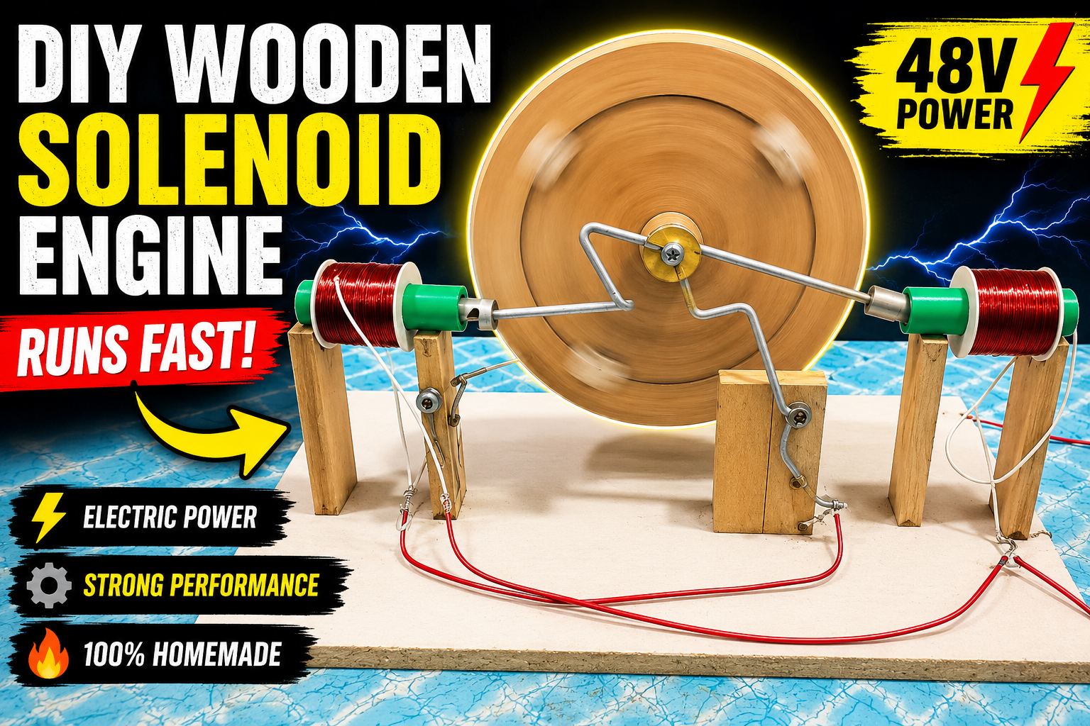
The project described in the source material demonstrates how a simple wooden structure, PVC pipes, copper wire coils, metal shafts, and a basic switching mechanism can be transformed into a fully operational engine powered by electromagnetism.
In this comprehensive guide, we will explore every major stage of building a DIY wooden solenoid engine, explain how the system works, discuss the materials required, and highlight important engineering principles that make the engine operate efficiently.
Understanding the Working Principle of a Solenoid Engine
Before starting construction, it is important to understand how a solenoid engine works. A solenoid is an electromagnetic coil that generates a magnetic field when electric current flows through it. This magnetic field can attract or repel a metal component positioned inside or near the coil.
In a solenoid engine, electromagnetic force replaces the combustion process used in traditional engines. When electricity passes through the coil, a piston-like metal component is pulled into the center of the solenoid. This linear movement is then converted into rotational motion using a crankshaft mechanism connected to a flywheel or wheel.
The engine described in the project uses two solenoid coils working together in sequence. Each coil energizes at specific moments during wheel rotation, creating continuous motion. The timing is controlled through a simple mechanical contact system that automatically switches power on and off as the wheel rotates.
One of the biggest advantages of this design is its simplicity. Unlike complex electronic controllers, sensors, or microprocessors, the engine uses a brass contact and metal wire switching arrangement to synchronize coil activation. This makes the project highly accessible for beginners.
Educationally, a wooden solenoid engine demonstrates several important concepts:
- Electromagnetic force
- Electrical circuits
- Mechanical motion conversion
- Crankshaft operation
- Flywheel momentum
- Energy transfer systems
- Basic automation mechanisms
For students and engineering enthusiasts, building such an engine provides practical experience that textbooks alone cannot deliver. Watching electromagnetic energy create physical movement helps transform theoretical knowledge into hands-on understanding.
The project also showcases how common materials can be used creatively. Instead of expensive industrial components, the design relies on PVC pipe, copper wire, wood, bearings, metal rods, and simple hardware. This makes it an affordable yet highly educational engineering project.
Preparing the Mechanical Components and Piston Assembly
The foundation of every engine is its mechanical system. In this project, the first major task involves creating the piston components that interact with the solenoid coils.
The process begins with selecting a metal shaft that fits smoothly inside a PVC pipe. The shaft must move freely while maintaining proper alignment. Two sections approximately 5 centimeters long are cut from the shaft and carefully marked at their centers. Holes are drilled into each piece to allow future mechanical connections.
After drilling, the shaft pieces are shaped using a grinder. Material is removed from the center portion, creating a profile similar to a piston. Precision during this stage is important because balanced piston components help reduce vibration and improve engine efficiency.
The shaping process requires patience. Removing too much material can weaken the component, while uneven grinding may cause instability during operation. Once the desired shape is achieved, sharp edges and burrs should be removed to ensure smooth movement inside the mechanism.
Several engineering considerations make this step critical:
Proper Balance
Matching dimensions between the two piston components ensures symmetrical operation. Imbalances can create unwanted stress on the crank mechanism and bearings.
Smooth Surface Finish
A smoother piston surface reduces friction and improves movement within the coil assembly.
Accurate Hole Placement
Centered holes help maintain alignment throughout the engine cycle.
Consistent Weight Distribution
Equal weight between piston assemblies contributes to smoother rotational motion.
The pistons serve as the moving elements that respond to electromagnetic force. Every time a coil energizes, the magnetic field attracts the piston. This motion ultimately drives the wheel through the crank mechanism.
Although these components appear simple, they are among the most important parts of the entire engine. Their precision directly affects overall performance, reliability, and efficiency.
Building Powerful Solenoid Coils for Electromagnetic Motion
The heart of the engine lies in its solenoid coils. These coils convert electrical energy into magnetic force, providing the power necessary to move the pistons.
Construction begins by preparing PVC pipe sections that serve as coil formers. Two PVC sections approximately 10 centimeters long are cut, and additional components are modified to create space for winding copper wire. Circular PVC plates are attached to each end of the pipe sections, forming spool-like structures that keep the wire neatly organized during winding.
Once the coil formers are prepared, the winding process begins.
The project uses 0.51 mm enamel-coated copper wire. This wire size provides a good balance between resistance, current handling capability, and magnetic field strength. The wire is wound evenly across the available space between the side plates.
Several factors influence coil performance:
Number of Turns
More turns generally produce a stronger magnetic field, although resistance also increases.
Wire Diameter
Thicker wire can carry more current but occupies more space.
Winding Consistency
Uniform winding creates a more stable magnetic field.
Coil Length
The length of the winding affects magnetic field distribution.
Maintaining constant tension during winding is essential. Loose turns can reduce efficiency and create uneven magnetic fields. Each turn should sit closely against the previous turn without overlapping.
After completing the first coil, the process is repeated for the second coil. Both coils should be as identical as possible to ensure balanced engine operation.
The finished solenoids become the engine's power-producing units. When energized, they create powerful magnetic fields capable of pulling the piston components into their centers.
This stage demonstrates a fundamental principle of electrical engineering: the conversion of electrical energy into mechanical motion through electromagnetism. It is the same principle used in relays, actuators, electric motors, and industrial automation systems around the world.
Constructing the Wooden Wheel, Shaft, and Bearing System
With the solenoid coils completed, attention shifts to building the rotating assembly that converts linear piston movement into rotational energy.
The wheel begins as a circular wooden disc cut from a wooden plate. Careful measurement and marking ensure the wheel remains balanced. Four evenly spaced holes are drilled around the wheel to maintain symmetry and improve appearance.
After cutting the wheel, the edges are sanded smooth and the center location is carefully identified. Accurate center marking is critical because even slight errors can create wobbling during operation.
The wheel serves several important functions:
Energy Storage
The wheel stores rotational energy between power strokes.
Momentum Generation
Once spinning, momentum helps carry the engine through periods when no coil is actively pulling a piston.
Speed Stabilization
A heavier wheel can reduce fluctuations in rotational speed.
Motion Transfer
The wheel transfers power from the pistons to the rotating shaft.
Next, bearings are installed into wooden support blocks. Bearings dramatically reduce friction and allow smooth rotation. The support blocks are mounted onto a wooden base, ensuring precise alignment.
The shaft is then inserted through the bearings and connected to the wheel assembly. Proper alignment is essential for minimizing resistance and preventing excessive wear.
A well-designed bearing system offers several benefits:
- Reduced friction
- Longer component life
- Smoother operation
- Higher rotational speeds
- Improved efficiency
This stage highlights the importance of mechanical engineering in electrical projects. Even the strongest solenoids cannot compensate for poorly aligned shafts or excessive friction. Mechanical precision is just as important as electrical performance.
Once assembled correctly, the wheel should rotate freely with minimal resistance, creating the foundation for the engine's motion system.
Designing the Crank Mechanism and Motion Conversion System
One of the most fascinating aspects of the project is the crank mechanism that converts straight-line piston movement into rotational motion.
A thin metal rod is shaped into a crank using pliers and bending tools. This crank connects the piston assemblies to the rotating wheel. As the piston moves in and out of the solenoid, the crank transforms that linear motion into circular movement.
This concept is widely used in many machines, including:
- Automobile engines
- Steam engines
- Air compressors
- Pumps
- Industrial machinery
The wheel receives a drilled mounting point positioned approximately 5 centimeters from the center. This offset location creates the leverage required for converting piston travel into rotational force.
Several design principles influence crank performance:
Throw Distance
The distance from the wheel center to the crank connection determines piston stroke length.
Mechanical Advantage
Proper geometry maximizes energy transfer.
Smooth Motion
Balanced crank design reduces vibration.
Reliable Connections
Strong joints ensure long-term durability.
When assembled correctly, the pistons move back and forth while the wheel rotates continuously. The crank serves as the critical link between electromagnetic force and usable rotational power.
This stage often gives builders their first opportunity to manually rotate the mechanism and observe how all components interact. It is an excellent demonstration of classical mechanical engineering principles that have been used for centuries.
Even though the project is relatively simple, it effectively illustrates how complex machines convert energy from one form into another through carefully designed linkages and motion systems.
Wiring, Synchronization, Testing, and Performance Optimization
The final stage transforms the assembled machine into a functioning engine.
The two solenoid coils are mounted facing each other on the wooden frame. Their positioning is extremely important because the pistons must move smoothly into and out of the coil centers. Proper alignment maximizes magnetic attraction and improves efficiency.
A brass contact is attached to the crank assembly, while thick silver wire forms a simple switching mechanism. As the wheel rotates, the brass contact touches and separates from the wire at specific moments, automatically controlling power flow to the coils.
This ingenious mechanical timing system eliminates the need for electronic controllers.
The project uses a 48-volt power source to energize the coils. Each coil has its own switching arrangement, allowing them to activate in sequence rather than simultaneously. This sequential operation creates smoother motion and more continuous torque.
Key performance factors include:
Coil Timing
Accurate timing ensures maximum pulling force.
Contact Reliability
Clean electrical contacts improve efficiency.
Mechanical Alignment
Proper alignment reduces friction losses.
Power Supply Quality
Stable voltage provides consistent performance.
Wheel Momentum
A balanced wheel helps maintain rotation.
When power is applied, the first coil attracts its piston. As the wheel rotates, the contact system deactivates that coil and activates the second one. The process repeats continuously, creating a smooth cycle of electromagnetic power strokes.
According to the project demonstration, adding the second synchronized coil significantly increases rotational speed and overall engine performance. The more frequent power strokes provide smoother operation and better momentum retention.
Conclusion
A DIY wooden solenoid engine is far more than a simple hobby project. It is a practical demonstration of physics, engineering, mechanics, and electricity working together in a functional machine. By combining wooden construction techniques, electromagnetic coils, crank mechanisms, bearings, and mechanical switching systems, builders gain valuable hands-on experience with real engineering principles.
This project proves that impressive machines can be created using affordable materials and basic workshop tools. Whether you are a student learning about electromagnetism, a maker exploring new projects, or an engineering enthusiast looking for a unique build, a wooden solenoid engine offers an engaging and educational challenge.
Most importantly, it provides a clear visual demonstration of how electrical energy can be converted into mechanical motion—a principle that powers countless technologies throughout the modern world.

Discussion
No comments yet. Be the first to join the conversation!