
Introduction to the DIY 200V Wooden Electricity Generator
Building your own electricity generator is one of the most rewarding DIY engineering projects you can undertake. It combines woodworking, basic electrical engineering, precision assembly, and hands-on experimentation into a single project that is both educational and practical. In this guide, you'll learn how to build a 200V wooden electricity generator using simple materials such as wooden plates, powerful permanent magnets, hand-wound copper coils, bearings, and a steel shaft. Although the frame is constructed primarily from wood, the generator operates using the same scientific principles found in commercial alternators and electrical generators. This project is designed to help makers, hobbyists, students, and DIY enthusiasts better understand how electrical energy is produced through mechanical motion.
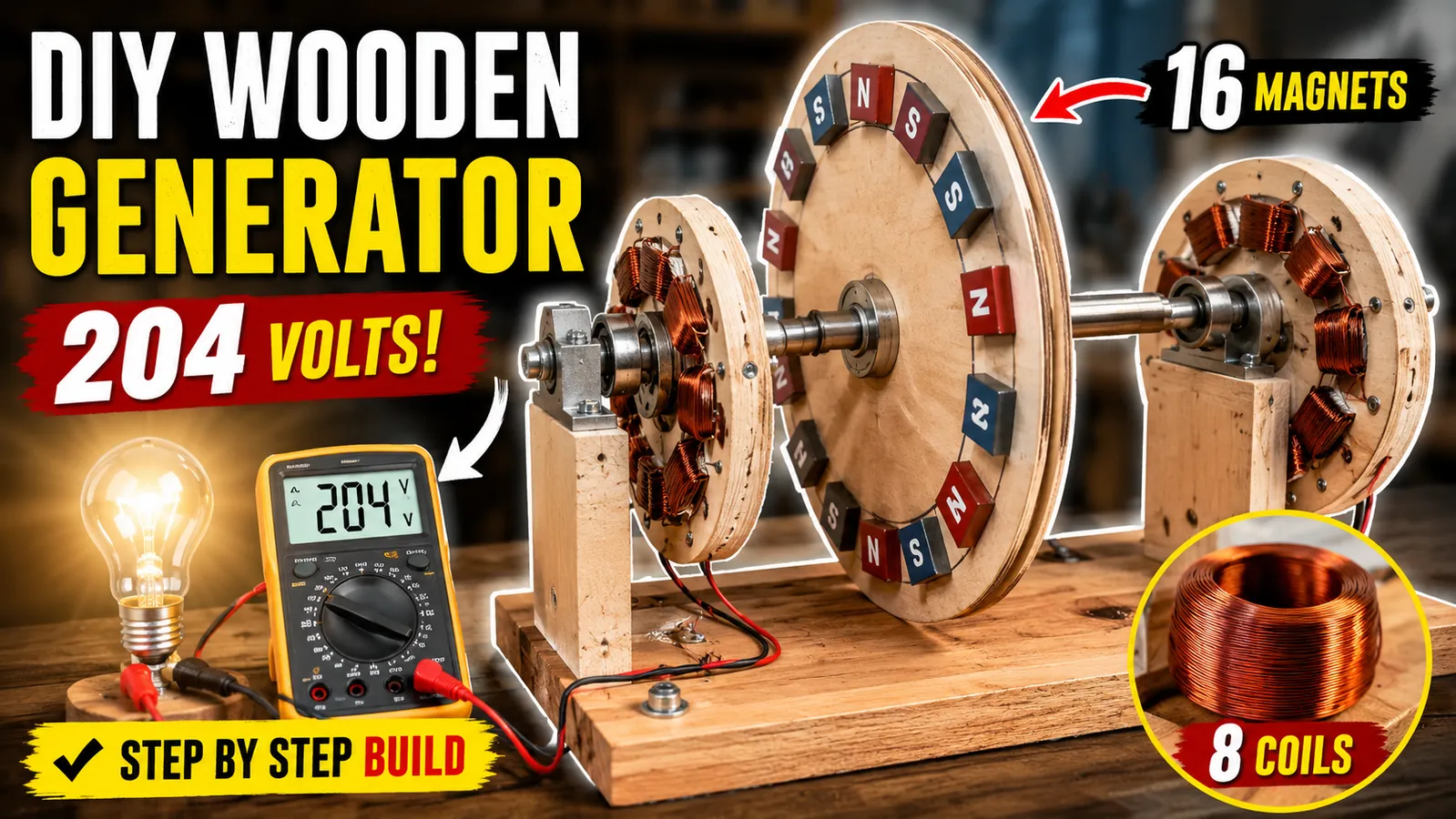
At the heart of every electrical generator lies the principle of electromagnetic induction. This phenomenon occurs when a changing magnetic field passes across a conductor, causing an electrical voltage to be induced in the wire. In this project, sixteen powerful permanent magnets are mounted around a circular wooden rotor. As the rotor spins, these magnets move past eight carefully wound copper coils that are fixed to a stationary wooden stator. Every time a north or south magnetic pole passes a coil, the magnetic field changes, producing alternating electrical voltage. The faster the rotor spins, the faster the magnetic field changes, resulting in a higher electrical output. This simple but powerful scientific principle has been used in power stations, wind turbines, hydroelectric plants, and portable generators for well over a century.
One of the greatest advantages of this project is that it demonstrates these engineering concepts using affordable and easy-to-work-with materials. Wood provides a lightweight, inexpensive, and highly customizable framework that allows builders to focus on learning the mechanical and electrical aspects of generator construction. Cutting, drilling, sanding, and assembling wooden components require only common workshop tools, making this an excellent project for anyone interested in woodworking or mechanical fabrication. At the same time, winding coils, arranging magnets, and assembling the electrical components provide valuable experience with real-world electrical engineering principles.
The generator itself consists of several carefully designed components that work together to convert mechanical energy into electrical power. The rotor is built from a 13-inch wooden plate carrying 16 evenly spaced permanent magnets arranged in an alternating north-south polarity pattern. The stator uses another wooden plate that supports eight identical copper wire coils, each wound with approximately 150 turns of 0.574 mm enamel-coated copper wire. A precision steel shaft runs through the center of the assembly and rotates on high-quality bearings to minimize friction and vibration. Additional wooden supports, mounting plates, adhesives, bolts, nuts, and electrical wiring complete the overall structure while ensuring proper alignment and durability throughout operation.
Throughout this guide, you'll follow the complete construction process from start to finish. You'll learn how to prepare the wooden rotor, accurately position the magnets, fabricate identical coil winding forms, wind consistent copper coils, assemble the stator, connect the electrical wiring, install the bearings, align the rotating components, and perform electrical testing. You'll also discover why precise spacing, balanced construction, proper magnetic polarity, and careful wiring play such important roles in generator efficiency and reliability. By the end of this tutorial, you'll not only have a functional DIY wooden electricity generator capable of producing approximately 200 volts under suitable operating conditions, but you'll also gain a much deeper understanding of the engineering principles that make modern electrical generators work. Whether your goal is education, experimentation, or expanding your DIY engineering skills, this project offers an engaging and practical introduction to the fascinating world of electricity generation.
Building the Rotor Assembly with 16 Alternating Magnets
The rotor is the heart of the wooden electricity generator because it carries the permanent magnets that create the changing magnetic field required for electricity generation. A well-built rotor ensures smooth operation, minimal vibration, and consistent electrical output. Before beginning assembly, prepare a high-quality 13-inch circular wooden plate that is perfectly round and free from cracks, warping, or other defects. The plate should be sanded smooth on both sides and balanced as evenly as possible. Since the rotor will spin at relatively high speeds during testing, any imbalance can create vibration, reduce efficiency, and place unnecessary stress on the bearings and shaft. Taking the time to prepare the wooden rotor correctly will greatly improve the overall performance and lifespan of the generator.
Once the wooden plate is ready, carefully locate and mark its exact center. Accurate centering is critical because even a slight offset can cause the rotor to wobble during rotation. Using a drill press or a carefully aligned hand drill, create a center hole that matches the diameter of the steel shaft. Insert the steel shaft through the hole and secure it firmly so it cannot shift while the generator is operating. The shaft should be perfectly perpendicular to the rotor plate, ensuring that the entire assembly spins true. Before continuing, rotate the rotor by hand to verify that it turns smoothly without noticeable wobble. If necessary, make small adjustments until the shaft and wooden plate are properly aligned.
The next step is preparing the mounting positions for the sixteen permanent magnets. Using a ruler, compass, or rotary dividing tool, divide the outer edge of the wooden rotor into 16 equal sections. Every magnet must occupy exactly one marked position, maintaining equal spacing around the entire circumference. Equal spacing is extremely important because it produces a balanced magnetic field and helps maintain consistent electrical output as the rotor spins. Uneven magnet placement can introduce vibration, create irregular voltage pulses, and reduce generator efficiency. Double-check all measurements before permanently attaching any magnets, since correcting mistakes after installation can be difficult.
With the positions marked, begin installing the magnets one at a time. Apply a strong, high-quality epoxy adhesive to the first marked location and firmly press the first magnet into place. Continue installing the remaining magnets while carefully maintaining the correct polarity pattern. The magnets must alternate between north pole facing outward and south pole facing outward all the way around the rotor. In other words, every north-facing magnet should be followed by a south-facing magnet, creating a repeating alternating magnetic field. Before fixing each magnet permanently, use another magnet or a magnetic polarity tester to verify its orientation. Taking a few extra seconds to confirm polarity helps prevent assembly errors that could significantly reduce the generator's performance.
After all sixteen magnets have been installed, inspect the rotor carefully from every angle. Confirm that every magnet sits at the same height, follows the alternating north-south arrangement, and remains securely bonded to the wooden surface. Allow the adhesive to cure completely according to the manufacturer's recommendations before moving the rotor. Once fully cured, rotate the assembly by hand again to check for smooth operation and proper balance. If minor imbalance is detected, small balancing adjustments can be made before final assembly. A properly balanced rotor not only reduces vibration and bearing wear but also allows the magnets to pass the stator coils with a uniform air gap. This consistent magnetic alignment produces a stronger changing magnetic field, resulting in smoother voltage generation, improved efficiency, and more reliable performance when the completed wooden generator is tested at higher rotational speeds.
Designing and Winding the Eight Copper Stator Coils
With the rotor assembly completed, the next major step is constructing the stator, which is responsible for converting the changing magnetic field into usable electrical energy. Unlike the rotating rotor, the stator remains stationary while the magnets pass over its copper windings. The quality of the stator directly affects the generator's voltage, efficiency, and overall performance. Begin by preparing another 13-inch circular wooden plate that will serve as the stator base. The surface should be flat, smooth, and accurately cut to ensure all components fit securely. Locate the exact center of the plate and mark it carefully, as this reference point will be used to position every coil with maximum precision. A well-prepared stator plate provides a stable foundation that helps maintain proper alignment throughout the entire assembly process.
Once the center has been established, divide the stator plate into eight equal sections around its circumference. Using a compass, protractor, or measuring jig, mark the exact locations where each stator coil will be installed. Every section must have identical spacing and the same distance from the center of the plate. Uniform positioning ensures that each coil experiences the same magnetic field as the rotor turns, resulting in balanced electrical output and smoother generator operation. Even small measurement errors can affect coil alignment, causing variations in voltage generation and reducing overall efficiency. Taking extra time to verify each marking before assembly will greatly improve the accuracy and performance of the finished generator.
The next task is building the wooden coil forms that will be used for winding the copper wire. Cut eight identical wooden pieces, ensuring every piece has the same length, width, and profile. Each form should feature a wider outer section and a narrower inner section, allowing the finished coils to fit neatly around the circular stator plate while leaving enough space for the rotating magnets to pass above them. After cutting the wooden forms, sand all edges until they are smooth to prevent damage to the enamel insulation on the copper wire during winding. Drill a centered hole through each wooden form so a bolt can be inserted to hold the winding assembly securely together. Next, attach PVC side plates to both sides of each wooden form using bolts and nuts. These PVC plates act as flanges that guide the copper wire into neat, evenly layered windings while preventing it from slipping off the edges during the winding process.
With the coil forms assembled, they are ready for winding. To achieve consistent results, mount each form onto a handheld drill or simple winding jig that allows smooth and controlled rotation. For this project, use 0.574 mm enamel-coated copper wire and carefully wind 150 turns onto each coil. Maintain steady wire tension throughout the entire process, ensuring every turn lies tightly against the previous one without crossing or overlapping unnecessarily. Count each turn carefully to guarantee that all eight coils contain exactly the same number of windings. Consistency is critical because differences in turn count or winding tension can produce unequal electrical characteristics, causing some coils to generate higher or lower voltage than others. After completing each coil, leave sufficient wire leads at both ends for later electrical connections and inspect the winding for any damaged insulation or loose turns before removing it from the coil form.
After all eight coils have been wound, compare them carefully to ensure they are virtually identical in size, thickness, shape, and wire count. Identical coils create a balanced magnetic response as the rotor magnets pass overhead, allowing the generator to produce smooth and consistent alternating voltage. Uniform windings also simplify the electrical wiring process because every coil contributes equally to the final output. If one coil is noticeably larger, smaller, or wound differently, it can disturb the magnetic balance of the stator and reduce the generator's efficiency. By investing time in accurate measurements, careful winding, and precise craftsmanship, you create a high-quality stator capable of delivering reliable electrical performance. These eight carefully constructed copper coils form the core of the generator's electrical system and play a crucial role in converting mechanical rotation into usable electrical energy.
Assembling the Generator and Wiring the Electrical System
After completing both the rotor and the eight stator coils, the next stage is assembling all the components into a fully functional electricity generator. This is one of the most important phases of the project because the mechanical alignment and electrical connections directly determine the generator's performance and reliability. Begin by preparing the stator plate for its center bearing. Carefully locate the exact center of the wooden stator plate and drill a hole that matches the outer diameter of the bearing. The bearing should fit snugly without excessive force or looseness. Once the hole is prepared, gently press the bearing into place and secure it firmly using adhesive or an appropriate retaining method if necessary. The center bearing provides smooth rotational support for the steel shaft, reducing friction while keeping the rotor accurately aligned during operation. A properly installed bearing also minimizes vibration and contributes to longer service life for the entire generator.
With the bearing installed, the stator plate is ready to receive the finished copper coils. Position each of the eight identical coils onto the previously marked locations around the circular plate. Every coil should be centered within its designated section and oriented in the same direction to maintain consistent magnetic interaction with the rotating magnets. Take your time to verify that the spacing between adjacent coils remains equal all the way around the stator. Once satisfied with their placement, secure each coil firmly using a high-strength adhesive or suitable fasteners. Apply even pressure while the adhesive cures to prevent the coils from shifting. Properly mounted coils are essential because any movement during operation can alter the air gap, reduce efficiency, or eventually damage the electrical wiring. After installation, perform a final visual inspection to confirm that all coils sit at the same height and are securely attached to the stator plate.
The next step is connecting the coils to create the generator's electrical output. Following the chosen wiring configuration, connect the end wire of the first coil to the beginning wire of the second coil, then continue this sequence from the second coil to the third, the third to the fourth, and so on until all eight coils are connected in series. This series arrangement combines the voltage produced by each individual coil to achieve a higher total output. Before making every connection, carefully remove the enamel insulation from the wire ends using fine sandpaper or a scraping tool to expose clean copper. Solder or securely join each connection to ensure low electrical resistance and dependable performance. Once every joint has been completed, cover the exposed conductors with heat-shrink tubing or high-quality electrical insulation tape to protect against short circuits, moisture, and accidental contact. Neatly route and secure the wiring to prevent movement or rubbing against rotating components during operation.
After completing the stator wiring, the rotor can be installed above the coil assembly. Carefully slide the steel shaft through the center bearing while ensuring that the sixteen permanent magnets pass directly over the stator coils without making physical contact. Maintaining a uniform air gap between the magnets and coils is critical for efficient electromagnetic induction. If the gap is too large, the magnetic field reaching the coils becomes weaker, reducing voltage output. If the gap is too small, the magnets may strike the coils during rotation, causing mechanical damage and potentially destroying the generator. Slowly rotate the rotor by hand to verify that it spins freely without rubbing or interference. Make any necessary alignment adjustments before permanently tightening all mounting hardware.
To improve stability and mechanical strength, install a second wooden support plate beneath the stator assembly and fit an additional bearing directly below the first one. This double-bearing design supports the steel shaft from both sides, greatly improving alignment while reducing shaft deflection and vibration at higher rotational speeds. Tighten all structural fasteners evenly and inspect the completed assembly from every angle to ensure the rotor remains perfectly centered above the stator. Finally, rotate the generator by hand several times to confirm smooth, silent operation and consistent clearance between every magnet and coil. Careful attention to mechanical alignment, secure electrical wiring, proper insulation, and a precisely maintained air gap ensures the completed generator operates efficiently, safely, and reliably during electrical testing.
Testing the Generator and Measuring Electrical Output
With the mechanical assembly complete and all electrical connections securely in place, the final stage of the project is testing the generator to verify that it produces electricity as intended. Careful testing not only confirms that the generator is functioning correctly but also provides valuable insight into how rotor speed, magnetic field strength, and coil design influence electrical output. Before applying any rotational force, perform a complete inspection of the generator. Check that all bolts and fasteners are tight, the bearings rotate freely, the magnets are firmly attached, and every electrical connection is properly insulated. Verify that the rotor spins without contacting the stator coils and that the air gap remains uniform around the entire assembly. Completing these safety checks helps prevent mechanical damage and ensures accurate electrical measurements during testing.
Begin the first test by connecting a digital voltmeter to the generator's output terminals. Select an appropriate AC voltage range if your generator is designed to produce alternating current. Once the measuring equipment is connected, slowly rotate the rotor by hand while observing the voltmeter. Even at relatively low rotational speeds, the movement of the sixteen alternating magnets past the eight copper coils should generate a measurable voltage. Although the output will be relatively small during hand rotation, this initial test confirms that electromagnetic induction is occurring and that the wiring, coil polarity, and magnetic arrangement are functioning correctly. If no voltage is detected, stop the test and carefully inspect the electrical connections, magnet polarity, and coil wiring before continuing with higher-speed testing.
After confirming basic operation, increase the rotor speed using an electric drill coupled securely to the steel shaft. A drill provides a stable and consistent rotational speed, allowing the generator to operate much faster than it can by hand. As the drill accelerates the rotor, the permanent magnets pass the stator coils more rapidly, increasing the rate of magnetic flux change. According to the principles of electromagnetic induction, this faster change in magnetic field induces a higher electrical voltage within the copper windings. Observe the voltmeter as the rotational speed increases. Under suitable operating conditions and with accurate construction, the generator can produce an output of approximately 200 volts at higher RPM. This significant increase in voltage clearly demonstrates the direct relationship between rotor speed and electrical generation. The faster the rotor turns, the greater the voltage produced, provided the generator remains within its safe mechanical operating limits.
Once the voltage output has been verified, perform a practical load test to demonstrate that the generator can deliver usable electrical power. Disconnect the voltmeter if necessary and connect a suitable light bulb or other compatible electrical load to the generator's output terminals. Double-check all wiring connections before beginning the test. Start the drill again and gradually increase the rotor speed until the generator reaches its operating range. As the magnets rotate past the coils, the generator begins supplying electrical energy to the connected load. If the assembly has been constructed correctly, the light bulb will illuminate, providing clear visual confirmation that the generator is converting mechanical energy into usable electricity. This simple demonstration highlights the successful interaction between the rotor, magnets, coils, and electrical wiring while showcasing the practical application of the completed DIY generator.
The final testing stage also offers an excellent opportunity to evaluate the generator's overall performance and identify possible improvements. Observe how changes in rotational speed affect both the voltage reading and the brightness of the connected light bulb. Higher RPM generally results in increased voltage and greater power output, while slower speeds produce lower electrical output. Listen for unusual noises, check for excessive vibration, and monitor the temperature of the bearings and electrical connections during extended operation. Smooth, quiet rotation with stable voltage readings indicates accurate alignment and quality craftsmanship. If vibration or inconsistent output is observed, inspect the rotor balance, magnet positioning, coil alignment, and electrical joints for possible adjustments. By carefully analyzing the test results, builders gain a deeper understanding of generator operation while confirming that the completed wooden electricity generator is functioning efficiently and safely under real operating conditions.
Safety Tips, Performance Optimization, and Final Thoughts
Congratulations on completing your DIY 200V wooden electricity generator. By carefully building the rotor, winding the stator coils, assembling the mechanical components, wiring the electrical system, and successfully testing the generator, you have created a working demonstration of electromagnetic induction using simple workshop materials. More importantly, you have gained practical experience with concepts that form the foundation of modern electrical power generation. This project demonstrates how mechanical energy can be converted into electrical energy through the interaction of permanent magnets and copper windings. Whether you built this generator for educational purposes, personal learning, or as a woodworking challenge, the finished project represents an excellent combination of craftsmanship, engineering, and scientific understanding.
Although the generator is relatively simple in design, it should always be operated with proper safety precautions. Rotating machinery, powerful magnets, power tools, and electrical voltage all present potential hazards if handled carelessly. Always wear appropriate personal protective equipment, including safety glasses, hearing protection when using power tools, and suitable work gloves during assembly. Keep loose clothing, jewelry, and long hair away from the rotating shaft and moving components. Before every test, inspect the generator for loose bolts, damaged wiring, cracked wooden parts, or magnets that may have shifted from their original positions. Never attempt to adjust the rotor or stator while the generator is spinning, and always disconnect any driving tool before performing maintenance or inspections. Maintaining a clean, organized workspace also helps reduce accidents and improves the quality of your work.
Special attention should also be given to handling permanent magnets and electrical connections. Strong neodymium magnets can snap together with significant force, potentially causing injuries or damaging nearby tools and electronic devices. Handle each magnet individually and keep them away from sensitive equipment such as mobile phones, credit cards, and storage devices. During electrical testing, remember that the generator can produce potentially hazardous voltages at higher rotational speeds. Avoid touching exposed conductors while the generator is operating, and ensure that every electrical joint is properly soldered and insulated using heat-shrink tubing or high-quality electrical tape. Always use measuring instruments that are rated for the expected voltage and operate the generator in a dry environment with adequate ventilation. Following these basic safety practices will make the project both safer and more enjoyable.
Once the generator is operating successfully, there are many ways to improve its performance and durability. Increasing construction accuracy is often more beneficial than simply adding more magnets or coils. Maintaining a perfectly balanced rotor, keeping a uniform air gap between the magnets and stator coils, and ensuring identical coil dimensions all contribute to smoother operation and higher efficiency. Upgrading to higher-quality bearings can reduce friction and extend the generator's service life, while stronger mounting brackets and reinforced wooden supports can improve structural stability during high-speed operation. Additional improvements may include applying protective finishes to the wooden components to resist moisture, organizing wiring with cable clips, or installing a protective cover over the rotating assembly. Builders who wish to expand the project further can experiment with different magnet sizes, alternative coil winding configurations, multiple stator layers, or regulated output circuits to explore how design changes influence generator performance.
This DIY wooden electricity generator is far more than a simple workshop project—it is a practical learning experience that combines woodworking, mechanical design, electrical engineering, and problem-solving into one rewarding build. Every stage of the construction process, from measuring and cutting the wooden components to winding identical coils and testing the finished generator, develops valuable technical skills that can be applied to many future engineering projects. Even if your primary goal is education rather than producing electrical power, the knowledge gained from building this generator provides a strong foundation for understanding motors, alternators, renewable energy systems, and industrial generators. Continue experimenting, refining your designs, and exploring new engineering ideas, because every project offers another opportunity to improve your craftsmanship and deepen your understanding of how electricity is generated. With patience, precision, and safe workshop practices, this project can serve as an inspiring introduction to the fascinating world of electrical generation and hands-on engineering.
Frequently Asked Questions (FAQs)
| Question | Answer |
|---|---|
| 1. How does a wooden electricity generator work? | A wooden electricity generator works by rotating permanent magnets past stationary copper coils, creating electrical voltage through electromagnetic induction. The wooden frame simply supports the mechanical components. |
| 2. Can a wooden generator really produce 200 volts? | Yes. With proper coil winding, strong magnets, and sufficient rotational speed, a well-built DIY generator can produce approximately 200 volts during testing. |
| 3. Why are 16 magnets used in this generator? | Sixteen magnets create multiple alternating magnetic poles around the rotor, producing a stronger and more consistent changing magnetic field for efficient electricity generation. |
| 4. Why are the magnets arranged in alternating north and south poles? | Alternating north and south poles create a continuously changing magnetic field as the rotor spins, which is essential for generating alternating current (AC). |
| 5. Why does the generator use eight copper coils? | Eight evenly spaced coils increase the generator's total voltage output and help create a balanced electrical waveform with smoother performance. |
| 6. What type of copper wire is used for the stator coils? | This project uses 0.574 mm enamel-coated copper wire, with approximately 150 turns wound onto each of the eight coils. |
| 7. Why is rotor balance important? | A balanced rotor reduces vibration, minimizes bearing wear, improves efficiency, and allows the generator to operate safely at higher rotational speeds. |
| 8. What is the purpose of the bearings? | Bearings support the rotating steel shaft, reduce friction, improve alignment, and allow the rotor to spin smoothly with minimal resistance. |
| 9. Why is the air gap between the magnets and coils important? | A consistent air gap ensures maximum magnetic flux passes through the coils without allowing the rotor to contact the stator, improving both efficiency and reliability. |
| 10. Can this generator power household appliances? | No. This project is primarily intended for educational and experimental purposes. Additional voltage regulation, frequency control, and safety systems would be required before powering household equipment. |
| 11. What happens if one magnet is installed backward? | Incorrect magnet polarity disrupts the magnetic field, reduces electrical output, and may significantly decrease the generator's overall performance. |
| 12. How can I increase the generator's output? | Performance can be improved by increasing rotor speed, using stronger magnets, optimizing coil design, improving rotor balance, reducing the air gap, and minimizing mechanical friction. |
| 13. Is this project suitable for beginners? | Yes. Beginners with basic woodworking and DIY experience can complete the project by following each step carefully and observing proper workshop safety practices. |
| 14. What safety precautions should I follow? | Always wear safety glasses, keep hands away from rotating parts, handle strong magnets carefully, insulate electrical connections properly, and never touch exposed wires while the generator is operating. |
| 15. What can I learn from building this DIY generator? | This project teaches woodworking, mechanical assembly, coil winding, magnet alignment, electrical wiring, electromagnetic induction, generator design, and practical engineering problem-solving skills. |
Conclusion
Building a DIY 200V wooden electricity generator is an excellent way to combine woodworking skills with the fascinating science of electrical engineering. Throughout this project, you've learned how to construct a balanced wooden rotor, correctly install sixteen alternating permanent magnets, wind eight identical copper stator coils, assemble the complete generator, and test its electrical output. Every step demonstrates the fundamental principle of electromagnetic induction, showing how mechanical motion can be converted into usable electrical energy through careful design and precision craftsmanship.
Beyond creating a functional generator, this project provides valuable hands-on experience with measuring, cutting, drilling, coil winding, mechanical alignment, and electrical wiring. It also highlights the importance of accuracy, patience, and safe workshop practices, all of which are essential skills for anyone interested in DIY engineering or renewable energy technologies. Even small improvements in magnet placement, coil consistency, rotor balance, and mechanical alignment can significantly enhance the generator's overall efficiency and reliability.
Whether you're a student, hobbyist, woodworker, or electronics enthusiast, this project serves as an outstanding educational platform for understanding how real-world generators operate. The knowledge gained from building this wooden generator can be applied to more advanced projects, including wind turbines, bicycle generators, hydroelectric systems, and custom alternators. By continuing to experiment with different coil configurations, stronger magnets, improved bearings, and optimized designs, you can further develop your engineering skills while exploring new methods of generating electricity.
We hope this complete guide has inspired you to build your own wooden electricity generator and deepen your understanding of electrical power generation. Remember to always work safely, use quality materials, and enjoy the learning process. Every successful project builds confidence, expands your technical knowledge, and opens the door to even more exciting DIY engineering creations in the future. Happy building!

Discussion
No comments yet. Be the first to join the conversation!