
How To Make a 310 Volt Electricity Generator: New Experiment Guide
Electricity generation has fascinated engineers, hobbyists, and inventors for centuries. From Faraday's legendary coil experiments in the 1830s to today's cutting-edge renewable energy systems, producing electrical power continues to inspire new experiments around the world.
One of the most exciting DIY electrical experiments trending in the maker community right now is building a 310 volt electricity generator. Whether you're an electronics enthusiast, a student exploring electromagnetic induction, or a hobbyist looking for your next weekend project, understanding how to make a 310V generator opens a door to deep practical knowledge about AC power, rectification, and motor-based generation.
In this comprehensive guide you'll find the science behind 310 volt DC output, the key components you need, a step-by-step build process, critical safety precautions, troubleshooting tips, and real-world applications — everything you need to successfully complete this new experiment.
When standard AC mains power — typically 220V AC in countries like Pakistan, India, and the UK — is passed through a full-wave rectifier circuit and smoothed with capacitors, the resulting DC voltage equals approximately the peak voltage of the AC waveform. For 220V AC, peak voltage works out to 220V multiplied by the square root of 2, giving approximately 311V DC, commonly rounded to 310V DC. This is why 310V DC is a critically important figure in power electronics — it forms the internal DC bus of variable frequency drives, solar inverters, motor speed controllers, uninterruptible power supplies, and switch-mode power supplies found in virtually every electronic device you own.
A 310 volt generator experiment typically takes one of two approaches: building a motor-driven AC alternator that outputs roughly 220V AC and then rectifying it to approximately 310V DC, or using a permanent magnet DC motor as a generator combined with a voltage multiplier or boost circuit to reach 310V. Both approaches are genuinely educational. This guide focuses on the motor-as-generator combined with rectifier approach, which is the most popular new experiment method seen in electronics workshops and maker communities.
Why This 310 Volt Generator Experiment Is Trending in 2024
Search interest in DIY electricity generators has surged in recent years for several compelling reasons. Rising electricity costs are pushing people to explore off-grid and backup power solutions. YouTube and online maker communities are showcasing high-voltage generator builds that attract millions of views. STEM education programs are increasingly encouraging hands-on experiments with real-world voltage levels. And the growing field of power electronics education demands that students understand the 310V DC bus — a concept essential for anyone learning inverter design or motor control.
This particular experiment sits at a practical sweet spot. It is high enough to be genuinely useful and educational, yet achievable with relatively accessible components available from any electronics supplier. Understanding how 310V is generated and controlled gives you direct insight into how the power electronics inside your air conditioner, electric vehicle charger, solar inverter, and industrial motor drives actually function at the component level.
The experiment is also visually dramatic and deeply satisfying. Watching a spinning motor generate real high voltage that lights up a voltmeter to 310V gives a visceral understanding of electromagnetic induction that no textbook diagram can match. This combination of accessibility, educational value, and hands-on excitement is exactly why the 310 volt generator experiment has become one of the most searched DIY power electronics projects online.
Components and Tools You Need to Build a 310 Volt Generator
Before starting your build, gather all components carefully. Always source from reputable suppliers and verify voltage ratings before purchasing. Using underrated components in a high-voltage project is one of the most dangerous mistakes a builder can make.
For the core electrical components you will need a permanent magnet DC motor rated between 12V and 24V with a high RPM specification — this will serve as your AC generator source when spun mechanically. You also need a mechanical drive source, which can be either a petrol engine or a second electric motor, to spin the generator motor at high speed. A full-wave bridge rectifier rated at 400V and at least 10 amperes is required to convert the AC output to DC — the KBPC1010 module is a popular choice for this application. Two to four electrolytic filter capacitors rated at 400V and 1000 microfarads each will smooth the rectified DC into stable 310V output. An optional DC-DC boost converter module rated up to 400V can be added if your generator output needs boosting to reach the full 310V target.
For measurement and protection you need a digital multimeter or voltmeter rated at 600V CAT III or higher, high-voltage rated wire of at least 1.5 square millimetres, a fuse holder with a 5 ampere fuse for overcurrent protection, and a coupling mechanism such as a belt, direct shaft coupling, or flexible coupler to connect the drive source to the generator motor. Mount everything on an insulated enclosure made from plastic or wood.
Safety equipment is absolutely non-negotiable for this project. Before starting your build, obtain insulated rubber gloves rated for high voltage, safety goggles, insulated screwdrivers and pliers, a non-contact voltage tester, and a fire extinguisher positioned nearby. Do not begin any wiring without this equipment in hand.
The Science Behind How a 310 Volt Generator Produces Power
Understanding the physics at every stage makes you a significantly better and safer builder. Here is what happens inside your generator circuit from mechanical rotation all the way to stable 310V DC output.
The first stage is electromagnetic induction. When a permanent magnet motor is spun mechanically, the magnetic field of the rotor cuts through the stator windings, inducing an alternating current by Faraday's Law of Electromagnetic Induction. The mathematical relationship states that induced EMF equals the number of coil turns multiplied by the rate of change of magnetic flux. The practical implication is straightforward: the faster you spin the motor, the higher the induced voltage and the higher the output frequency. This is why controlling RPM is the primary way to control output voltage in this experiment.
The second stage is AC to DC rectification. The AC output from the spinning motor is fed into a full-wave bridge rectifier — four diodes arranged in a bridge configuration. This converts both the positive and negative halves of the AC waveform into pulsating DC. The rectifier does not smooth the output — it simply ensures current always flows in one direction.
The third and final conversion stage is capacitor filtering. The pulsating DC from the rectifier charges large electrolytic capacitors up to the peak voltage of the AC waveform. For a 220V AC input, this peak is 220 multiplied by 1.414, giving approximately 311V DC. The capacitors hold this charge and release it steadily, providing the smooth, stable 310 volt DC output that is the goal of this entire experiment. This DC bus voltage is identical in principle to the internal bus voltage found inside every commercial inverter and variable frequency drive on the market.
Step-by-Step Build Process for Your 310 Volt Generator
Follow these steps carefully and never rush a high-voltage project. Each step builds on the last, and skipping any step introduces serious risk.
Begin by preparing your workspace. Set up a clean, dry workbench with good lighting. Ensure no water, humidity, or conductive materials are present. Place a rubber mat on the floor and have all your safety equipment on before touching any components.
Next, mount the generator motor securely to your base frame using bolts and brackets. Vibration at high RPM can loosen mounts and cause dangerous misalignment, so this step requires firm, tight fastening.
Then connect your drive motor or petrol engine to the generator motor shaft using a flexible coupler or belt-and-pulley system. Ensure precise alignment to prevent bearing wear and excessive vibration. A belt drive is particularly useful because it also provides a degree of electrical isolation between the drive source and the generator output. Gradually increase drive speed while measuring output with your multimeter until the generator produces approximately 220V AC.
Wire the AC output terminals of the generator motor to the two AC input pins of your bridge rectifier. Use high-voltage rated wire throughout and make secure, properly insulated connections. Confirm your bridge rectifier is rated for at least 400V and 10 amperes before making any connections.
Connect your electrolytic capacitors in parallel across the DC output of the bridge rectifier, positive terminal to positive and negative to negative. Use at least two 1000 microfarad 400V capacitors for adequate filtering. This step requires absolute attention to polarity — electrolytic capacitors connected in reverse at high voltage will rupture explosively.
Wire your fuse in series with the positive DC output line. Never operate any high-voltage circuit without overcurrent protection. Connect a digital voltmeter across the output terminals so you can monitor voltage in real time throughout the experiment.
Place the rectifier, capacitors, and all wiring inside your insulated enclosure. Only the input shaft coupling, drive connection, and clearly labeled shrouded output terminals should be accessible from outside. This is not optional — it is a fundamental safety requirement for any high-voltage build.
For your first power-up test, put on insulated gloves and safety goggles, have a second person present if possible, and gradually spin the drive motor up to operating speed. Watch the voltmeter rise toward 310V DC. If you observe sparking, smoke, or any unexpected reading, immediately stop the drive motor and disconnect everything before investigating.
Safety Rules, Troubleshooting, and Real-World Applications of 310 Volt Power
Working with 310 volts DC is extremely dangerous and must never be treated casually. Unlike AC, DC does not have a zero-crossing point, which means it can sustain an arc and cause deeper tissue burns than equivalent AC voltages. A 310V DC shock can be and frequently is lethal.
There are several golden rules that must never be broken. Never work alone on a high-voltage project — always have someone present who can call for help or kill power in an emergency. Always discharge capacitors through a resistive bleed resistor of approximately 10 kilohms at 10 watts before touching any circuitry after power is removed — capacitors store lethal charge even when the generator is completely stopped. When probing live circuits, keep one hand in your pocket to prevent current flowing across your chest through your heart. Treat all terminals as live until verified dead with a non-contact voltage tester. Never bypass fuses or any overcurrent protection device under any circumstances. Ground the metal chassis of your enclosure to earth to protect against shock from insulation failures. Keep children and untrained persons completely away from the operating experiment.
For troubleshooting, if output voltage is too low the generator is spinning too slowly and you need to increase drive RPM. If output voltage is too high, reduce RPM using a speed controller. If voltage is unstable or flickering, add more filter capacitors in parallel. If the rectifier runs very hot, upgrade to a higher-rated module and add an aluminum heat sink. If any capacitor shows signs of swelling or bulging, immediately power down and replace it — a bulging capacitor is on the verge of catastrophic failure.
The real-world applications of this 310V DC bus knowledge are remarkably broad. Variable frequency drives used in industrial motor control internally rectify 220V AC to approximately 310V DC before generating variable-frequency output. Solar inverters use a 310 to 400V DC bus derived from panel strings. UPS systems maintain a high-voltage DC bus to power their output inverter stage. DC fast chargers for electric vehicles work with bus voltages in the 310 to 800V range. Switch-mode power supplies inside desktop computers, televisions, and home appliances all begin with a 310V DC rectified stage before their transformer section. By building and understanding this generator experiment, you gain direct hands-on insight into all of these technologies simultaneously — making this one of the highest-value practical experiments available in the field of power electronics education.
Frequently Asked Questions — How To Make 310 Volt Electricity Generator
| # | Question | Answer |
|---|---|---|
| 1 | What is a 310 volt electricity generator? | A 310 volt generator is a device that produces approximately 310V DC output by spinning a permanent magnet motor to generate AC, then converting it through a full-wave bridge rectifier and capacitor filter. This mirrors the internal DC bus voltage found in commercial inverters and VFDs. |
| 2 | Why does rectified 220V AC give 310V DC? | Because rectification captures the peak voltage of the AC waveform, not the RMS value. The formula is 220V × √2 = 311V, which is rounded to 310V DC. This peak voltage is stored and smoothed by capacitors in the output stage. |
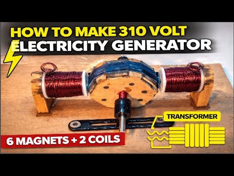
| 3 | How many magnets and coils are needed? | This experiment uses 6 permanent magnets and 2 copper wire coils. The magnets are mounted on the rotor disc and the coils sit on either side as the stator, generating AC current as the rotor spins between them. |
| 4 | What type of motor works best as a generator? | A permanent magnet DC motor rated between 12V and 24V with a high RPM specification works best. When spun mechanically, it generates AC output that can be rectified to reach 310V DC with the right drive speed. |
| 5 | Is a transformer required in this experiment? | Yes, a transformer is used in this design to step up the lower AC voltage produced by the coils to approximately 220V AC before rectification. This allows the rectifier output to reach the target 310V DC level. |
| 6 | How dangerous is 310 volts DC? | Extremely dangerous. Unlike AC, DC does not have a zero-crossing point, meaning it sustains an arc and causes deeper burns. A 310V DC shock can stop the heart and be fatal. Always use insulated gloves, safety goggles, and discharge capacitors before touching any part of the circuit. |
| 7 | What bridge rectifier should I use for this project? | Use a full-wave bridge rectifier module such as the KBPC1010, rated at a minimum of 400V and 10 amperes. Always choose a rectifier rated well above the operating voltage to provide a safe working margin. |
| 8 | What capacitors are needed to filter the 310V output? | Use two to four electrolytic capacitors rated at 400V and 1000 microfarads each, connected in parallel across the DC output. Always verify polarity before connecting — reverse polarity at high voltage will cause the capacitors to rupture explosively. |
| 9 | Can this generator power household appliances directly? | No. The output is 310V DC, but household appliances require 220V AC. You would need an inverter circuit to convert the 310V DC back to 220V AC. This is exactly how commercial inverters work — the generator replicates their input stage. |
| 10 | What real-world devices use a 310V DC bus internally? | Many common devices use a 310V DC bus, including variable frequency drives (VFDs), solar inverters, UPS systems, DC fast chargers for electric vehicles, and the switch-mode power supplies (SMPS) inside computers, televisions, and home appliances. |

Discussion
No comments yet. Be the first to join the conversation!