
How to Make a 17kW Generator System from a 3HP Motor and 17kW Alternator with Full RPM Calculation
Important Note: The term "free energy generator" is scientifically incorrect. A 3HP motor cannot produce 17kW of electrical power without an external energy source. This article explains a pulley-driven generator setup and RPM calculations for educational purposes.
Introduction
Building a generator system using an electric motor and an alternator is a popular project among DIY enthusiasts, mechanics, and electrical hobbyists. Many people search for ways to connect a 3HP motor to a 17kW alternator using pulleys and belts while calculating the correct RPM required for efficient operation. Understanding pulley ratios and rotational speed is essential because an alternator must rotate at a specific speed to generate its rated voltage and power output.
In any motor-driven generator setup, the motor acts as the prime mover while the alternator converts mechanical energy into electrical energy. The challenge is determining the correct pulley sizes that will allow the alternator to reach its desired operating RPM. Incorrect pulley selection can result in low voltage output, overheating, excessive belt wear, or poor efficiency.
This guide explains a practical pulley arrangement similar to many workshop generator projects. We will walk through the complete RPM calculation process, show how pulley ratios affect speed, and explain how to determine alternator RPM accurately. These calculations can be applied to almost any motor-and-alternator combination.
Before starting construction, it is important to understand that power output is limited by the input power available from the motor. RPM calculations can increase or decrease rotational speed, but they cannot create additional energy. Proper pulley design simply ensures that available mechanical power is transferred efficiently to the alternator.
By following the calculations in this article, you can design a reliable belt-driven generator system and accurately predict alternator speed before assembling the machine.
Understanding the Components of the Generator System
A typical belt-driven generator setup consists of a motor, pulleys, belts, shafts, bearings, and an alternator. Each component plays a critical role in transferring power from the motor to the electrical generator.
The 3HP motor serves as the driving source. Most industrial 3HP induction motors operate at approximately 1450 RPM when connected to a 50Hz power supply. This speed becomes the starting point for all pulley calculations. Since alternato
rs often require different operating speeds, pulley ratios are used to adjust rotational speed accordingly.
The motor pulley is mounted directly on the motor shaft. As the motor rotates, the pulley drives a belt connected to a larger or smaller pulley on an intermediate shaft. Depending on the pulley sizes, speed may increase or decrease while torque changes in the opposite direction.
An intermediate shaft is commonly used when multiple speed changes are required. This shaft may carry two pulleys of different diameters, allowing the designer to create a two-stage transmission system. Such arrangements are often used when large speed changes are needed.
The alternator converts rotational energy into electrical energy. Most alternators require a specific RPM range to achieve their rated voltage and frequency characteristics. Therefore, matching motor speed to alternator requirements through pulley calculations is essential.
When all components are properly sized and aligned, the system can operate smoothly, efficiently, and with minimal belt wear. Understanding each component helps ensure that RPM calculations are applied correctly during the design process.
Basic RPM Formula for Pulley Calculations
The relationship between pulley diameter and rotational speed is governed by a simple formula:
Where:
- RPM₁ = Driving pulley speed
- D₁ = Driving pulley diameter
- RPM₂ = Driven pulley speed
- D₂ = Driven pulley diameter
This formula is based on the principle that belt speed remains constant across both pulleys. As pulley diameter increases, rotational speed decreases. Conversely, reducing pulley diameter increases rotational speed.
For example, if a motor rotates at 1450 RPM and uses a 2.5-inch pulley to drive a 9.5-inch pulley, the calculation becomes:
1450 × 2.5 ÷ 9.5 = 381.58 RPM
This means the driven pulley rotates at approximately 381 RPM. The larger pulley reduces speed while increasing torque.
The same formula can be applied repeatedly for multi-stage systems. After calculating the speed of one shaft, that RPM becomes the input speed for the next pulley stage. This allows accurate calculation of alternator speed regardless of how many pulleys are involved.
Understanding this formula is the foundation of all pulley-driven machine calculations. Once mastered, it can be used for generators, fans, pumps, compressors, woodworking machinery, and countless other mechanical systems.
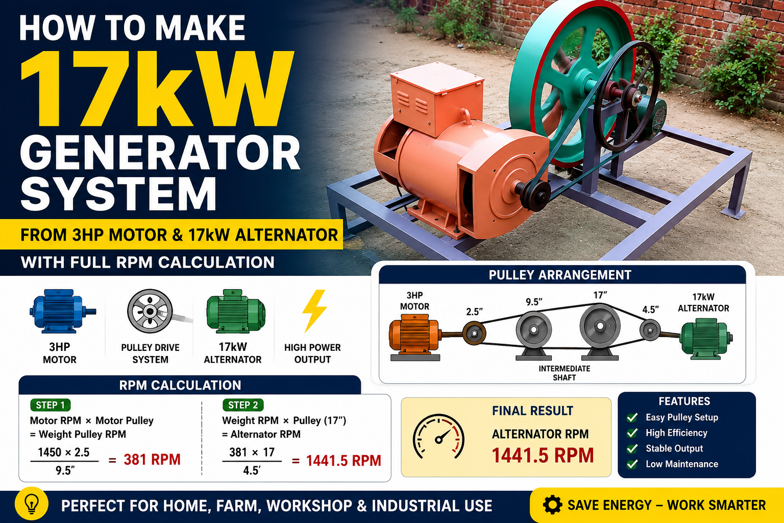
Full RPM Calculation for the 17kW Alternator Setup
Let's calculate the alternator RPM using the pulley arrangement shown in the example.
System Specifications
- Motor RPM = 1450
- Motor Pulley = 2.5 inches
- Weight Pulley = 9.5 inches
- Secondary Pulley = 17 inches
- Alternator Pulley = 4.5 inches
Step 1: Calculate Weight Pulley RPM
Using the pulley formula:
1450 × 2.5 = 3625
3625 ÷ 9.5 = 381.58 RPM
The weight shaft rotates at approximately 381 RPM.
Step 2: Calculate Alternator RPM
Now use the secondary pulley on the weight shaft:
381.58 × 17 = 6486.86
6486.86 ÷ 4.5 = 1441.52 RPM
Final alternator RPM:
1441.5 RPM
This means the alternator rotates at approximately 1441 RPM when the motor runs at 1450 RPM and the specified pulley sizes are used.
This method provides a highly accurate calculation and can be applied to any belt-driven machine. By changing pulley diameters, you can increase or decrease alternator speed to match operational requirements.
Building the Generator Frame and Pulley System
A strong frame is essential for maintaining pulley alignment and reducing vibration. Most DIY builders use steel angle iron, square tubing, or heavy-duty channel sections to construct the generator base. The frame should be rigid enough to support the motor, alternator, intermediate shaft, and bearings without flexing under load.
Begin by mounting the motor securely to an adjustable base plate. The adjustable mount allows belt tension to be set correctly after installation. Proper belt tension prevents slipping while reducing unnecessary stress on bearings.
The intermediate shaft should be supported by quality pillow block bearings. Accurate shaft alignment is critical because even slight misalignment can cause excessive vibration and premature belt wear. Ensure that all pulleys are positioned in the same plane before tightening set screws.
After installing the pulleys, fit the belts and check tension. Belts should be tight enough to prevent slipping but not so tight that they overload bearings. Rotate the system by hand before powering the motor to verify smooth operation.
Once the mechanical assembly is complete, electrical wiring can be connected according to the alternator manufacturer's specifications. Safety guards should be installed around all rotating components to prevent accidental contact during operation.
A properly constructed frame improves efficiency, reduces maintenance requirements, and extends the life of the entire generator system.
Power Limitations and Important Considerations
One of the most common misconceptions in DIY generator projects is the belief that pulley ratios can increase power indefinitely. While pulleys can change RPM and torque, they cannot create additional energy. The total output power of a system is always limited by the input power supplied to the motor.
A 3HP motor produces approximately 2.24kW of mechanical power under ideal conditions. After accounting for motor efficiency, belt losses, bearing friction, and alternator efficiency, the electrical output will be lower than the motor's mechanical input. Therefore, a 3HP motor cannot continuously drive a 17kW electrical load.
Pulley systems are excellent for matching RPM requirements, but they do not multiply power. Increasing alternator RPM through pulley ratios will reduce available torque proportionally. This is a fundamental law of mechanics and energy conservation.
When designing a generator system, always ensure that the motor has sufficient horsepower for the intended electrical load. Oversized alternators can be used, but their output will still be limited by the power available from the driving motor.
Understanding these principles helps avoid unrealistic expectations and leads to safer, more efficient generator designs. By combining accurate RPM calculations with realistic power requirements, builders can create reliable motor-driven generator systems that perform as expected.
Frequently Asked Questions (FAQs) About a 17kW Alternator and 3HP Motor Generator System
| # | Question | Answer |
|---|---|---|
| 1 | Can a 3HP motor produce 17kW of electrical power through a 17kW alternator? | No. A 3HP motor provides approximately 2.24kW of mechanical power under ideal conditions. It cannot continuously generate 17kW of electrical output because energy cannot be created from nothing. |
| 2 | What is the RPM of a typical 3HP induction motor? | Most 3HP induction motors operate at approximately 1450 RPM on a 50Hz power supply and around 1750 RPM on a 60Hz power supply. |
| 3 | Why are pulleys used between the motor and alternator? | Pulleys allow the rotational speed to be increased or decreased to match the alternator's required operating RPM while transferring power efficiently. |
| 4 | What formula is used to calculate pulley RPM? | The basic formula is: RPM₂ = (RPM₁ × Pulley Diameter₁) ÷ Pulley Diameter₂. This formula helps determine the speed of the driven pulley. |
| 5 | How was the alternator RPM of 1441.5 calculated? | First, calculate the intermediate shaft RPM: (1450 × 2.5) ÷ 9.5 = 381 RPM. Then calculate alternator RPM: (381 × 17) ÷ 4.5 = 1441.5 RPM. |
| 6 | Does increasing RPM with pulleys increase power output? | No. Increasing RPM decreases available torque. Pulleys change speed and torque ratios but do not increase total power. |
| 7 | What happens if the alternator RPM is too low? | The alternator may produce lower voltage, reduced frequency, poor performance, and insufficient electrical output for connected loads. |
| 8 | What happens if the belts are too loose? | Loose belts can slip, reduce efficiency, generate heat, wear prematurely, and cause inaccurate RPM transfer between pulleys. |
| 9 | Can the same RPM calculation method be used for other machines? | Yes. The pulley RPM formula can be used for generators, pumps, fans, conveyors, compressors, woodworking machines, and many other belt-driven systems. |
| 10 | What is the most important factor when designing a pulley-driven generator system? |
Conclusion
Building a pulley-driven generator system using a 3HP motor and a 17kW alternator can be an excellent project for learning about mechanical power transmission, pulley ratios, and RPM calculations. By selecting the correct pulley sizes and applying the proper RPM formulas, you can accurately determine the rotational speed of every shaft in the system and ensure that the alternator operates within its intended speed range.
In the example covered in this guide, a 1450 RPM motor driving a 2.5-inch pulley connected to a 9.5-inch pulley produces approximately 381 RPM on the intermediate shaft. Using a second-stage pulley arrangement with a 17-inch pulley and a 4.5-inch alternator pulley increases the final alternator speed to approximately 1441.5 RPM. These calculations demonstrate how pulley ratios can be used to increase or decrease rotational speed while maintaining efficient power transfer.
It is important to remember that pulleys can change RPM and torque, but they cannot increase the total power available in the system. The actual electrical output will always be limited by the mechanical power supplied by the motor and the efficiency of the overall setup. Proper pulley alignment, correct belt tension, strong frame construction, and accurate calculations are essential for reliable operation and long service life.
Whether you are designing a workshop generator, an experimental alternator setup, or any other belt-driven machine, understanding RPM calculations is the key to achieving optimal performance. With careful planning and accurate measurements, you can build a dependable system that operates smoothly, efficiently, and safely for years to come.

Discussion
No comments yet. Be the first to join the conversation!