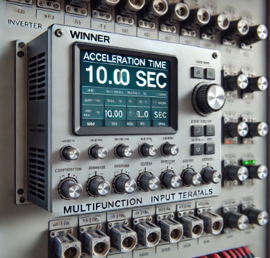
Setting the acceleration time on a Winner inverter is crucial for ensuring optimal performance and longevity of both the inverter and the connected motor. Acceleration time refers to the duration the inverter takes to ramp up the motor’s speed from zero to its maximum frequency. Proper configuration of this parameter ensures smooth startups, prevents mechanical stress, and avoids electrical faults.
Understanding Acceleration Time Of Winner inverter
Acceleration time is the period required for the inverter to increase the motor’s speed from standstill to its operating speed. Setting this time appropriately is vital to prevent overcurrent situations that can trip the inverter or cause damage. A shorter acceleration time results in a quicker start but demands more current, which might exceed the inverter’s capacity. Conversely, a longer acceleration time provides a gentler start, reducing the risk of overcurrent but delaying the motor reaching its desired speed.
Setting Acceleration Time on Winner Inverters
Winner inverters offer multiple acceleration and deceleration time settings, allowing users to tailor the performance to specific applications. These settings can be adjusted through the inverter’s multifunction input terminals. According to the information available:
Acceleration/Deceleration Time Selection 1: Set the multifunction input to value 7.
Acceleration/Deceleration Time Selection 2: Set the multifunction input to value 1A.
By configuring these settings, users can switch between different acceleration and deceleration times during operation, providing flexibility based on load requirements.
Automatic Acceleration/Deceleration Mode
Some inverters feature an automatic mode where the acceleration and deceleration times adjust based on the load. In this mode, the inverter modifies the ramp-up and ramp-down times within a specific range to accommodate varying load conditions. This ensures that the motor accelerates and decelerates smoothly without manual intervention.
Considerations for Optimal Acceleration Time
When configuring the acceleration time on a Winner inverter, consider the following:
Load Characteristics: Heavy loads may require longer acceleration times to prevent overcurrent faults.
Inverter Capacity: Ensure that the acceleration time set does not demand more current than the inverter’s rated capacity.
Application Requirements: Some applications may necessitate quick starts, while others may benefit from gradual acceleration to protect mechanical components.
Conclusion
Properly setting the acceleration time on a Winner inverter is essential for efficient and safe operation. By understanding the load requirements and the inverter’s capabilities, users can configure the acceleration parameters to achieve optimal performance and prevent potential faults.
Win- va /vc,s deceleration / acceleration time has 4 options , to switch between these time option , please set deceleration / acceleration time option 1 ,2 at multi function input .
setting value 7 = acceleration / deceleration time selection 1 .
setting value 1 a = acceleration / deceleration time selection 2 .
according to the deceleration / acceleration time option 1 , 2 ,s on/of , the selected deceleration / acceleration time is as follows the deceleration/ acceleration time can be switched during operation .
acceleration time selection 1=acceleration/deceleration time 2 = acceleration time =deceleration time.
off or not set = off or not set = acceleration time 1 c 1-01 = deceleration time 1 c 1- =02.
on = off or not set = acceleration time 2 c 1-03= deceleration time 2 c 1- =04 .
off or not set = on = acceleration time 3 c 1-05 =deceleration time 3 =c 1-06 .
on =on =acceleration time 4 c 1-07 =deceleration time 4 =c 1-08 .
Emergency stop ( setting value , 15 ,17 )
When emergency stop is selected , multi function input is on , the inverter will deceleration to stop according to the deceleration time set by c1-09 ( emergency stop time ) to release the emergency stop please set the operation command and emergency stop both to be off.
When emergency stop is at contact b , please set it as 17 .
setting value 15 : emergency stop ( a contact deceleration to stop according to c1-09 when it is in on status ).
setting value 17 : emergency stop (b contact decelerate to stop according to c1-09 when it is in off status).
f jog command /r jog command (setting value 12,13
for/rev jog frequency operation is allowed
setting value 12 = f jog command on forward operation when pressing jog frequency (d1-09_
setting value 13= R jog command on forward operation when pressing jog frequency (d1-09)
F jog command and f jog command is prior to the other frequency command . when f jog command and r jog command are in the status of on for above 500 ms the inverter will stop according to the setting of b1-03 (stop method selection ) it is acceptable that either f jog command or f jog command is set it will be in a single operation status when for/rev command are not input frequency command terminal 13/14 selection (setting value ,1f ) when this function is set at multi function input terminal 13 or 14 operation can be switched.
off: the main speed frequency command is the analog signal from terminal 13 .
on : the main speed frequency command is the analog signal from terminal 14 .


I like what you guys are up too. Such clever work and reporting! Carry on the superb works guys I have incorporated you guys to my blogroll. I think it’ll improve the value of my website 🙂
Yeah bookmaking this wasn’t a risky decision great post! .