Introduction
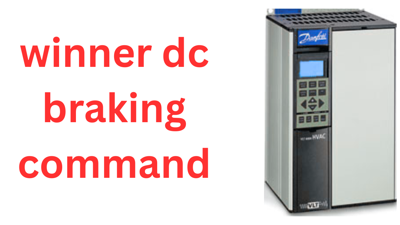
winner dc braking command In the rapidly evolving field of industrial automation, precision control and energy efficiency have become critical benchmarks. Among the core components that drive these standards is the DC inverter, which enables variable speed control of electric motors. Within this technology suite, the braking command plays an essential role in enhancing performance, safety, and operational responsiveness.
This article explores the Winner DC inverter braking command, a key feature in the Winner series of variable frequency drives (VFDs). We will dissect how the braking command works, why it’s significant, its real-world applications, and how it compares to traditional braking methods. Whether you’re an automation engineer, a maintenance technician, or a student of mechatronics, this guide will provide a detailed understanding of this vital industrial function.
Chapter 1: Understanding DC Inverter Technology
Before delving into braking commands, it is essential to understand the basic operation of DC inverters, particularly in the context of variable frequency drives (VFDs).
1.1 What Is a DC Inverter?
A DC inverter, in the context of industrial motor control, refers to a system that converts AC power into DC, then back into a variable AC output. This conversion allows motors to operate at different speeds and torques by adjusting the frequency and voltage of the output power.
1.2 Basic Components of a DC Inverter
Rectifier: Converts AC input to DC.
DC Bus: Intermediate circuit where DC voltage is filtered and stored.
Inverter: Converts DC back to variable AC.
Control System: Determines output frequency and voltage based on user inputs or automatic adjustments.
1.3 Why Use Inverters?
Energy Efficiency: Reducing energy consumption by matching motor speed to load requirements.
Process Control: Better control over production parameters such as conveyor speeds.
Reduced Mechanical Stress: Smooth acceleration and deceleration reduce wear and tear.
Chapter 2: Braking in Inverter Systems
In motor-driven systems, stopping or slowing down a motor is as important as accelerating it. Traditional methods use mechanical brakes, but in VFD systems, electronic braking is preferred for its responsiveness and reduced maintenance.
2.1 Why Braking Is Critical
During deceleration, motors act as generators. If not handled properly, the generated energy can damage the inverter or cause uncontrolled stops. Hence, braking systems are used to safely dissipate this energy.
2.2 Types of Braking in VFDs
Coasting Stop: Motor stops without any control; purely inertial.
Ramp Stop: Controlled deceleration via inverter command.
Dynamic Braking: Converts kinetic energy into heat using resistors.
Regenerative Braking: Sends energy back to the power grid or other systems.
Chapter 3: Introduction to Winner DC Inverter Braking Command
The Winner series of DC inverters, developed by Winner Automation, comes equipped with several braking features that improve motor control, particularly in high-performance applications. Among these is the braking command — a set of programmable parameters and functions that initiate and control the braking process.
3.1 What Is the Braking Command?
The braking command is a feature within the inverter’s firmware that controls how the inverter engages braking resistors or initiates regenerative braking when a stop is commanded.
3.2 How the Braking Command Works
When a deceleration is required, the inverter senses the DC bus voltage.
If the voltage exceeds a set threshold, indicating regenerative energy, the braking command activates.
The system either diverts excess energy to a braking resistor or adjusts motor parameters to dissipate energy safely.
3.3 Activation Methods
Manual Activation: Via digital inputs or operator panel.
Automatic Activation: Based on load, motor speed, or deceleration profiles.
Programmable Triggers: Set via software or keypad based on operation logic.
Chapter 4: Technical Specifications
Each Winner inverter model may support slightly different braking profiles, but most follow common guidelines.
4.1 Parameters Related to Braking Command
Braking Enable (BEn): Turns braking function on or off.
Braking Start Voltage (Bsv): Voltage level at which braking is triggered.
Braking Duty Cycle (BdC): Limits duration to prevent overheating.
Braking Resistor Value (BrR): Ohmic value of external resistor used.
4.2 Hardware Support
Compatible with external braking modules or internal braking transistors.
Some models support regenerative braking units.
4.3 Software and Communication
Integration via Modbus, CANopen, or Ethernet/IP.
Configurable through WinnerDrive software or HMI interfaces.
Chapter 5: Benefits of Using Winner’s Braking Command
Implementing the braking command provides a host of advantages, especially in demanding industrial environments.
5.1 Enhanced Motor Control
Braking commands offer smoother deceleration, reducing mechanical stress and preventing motor overshoot.
5.2 Safety Improvements
Quick, controlled stops can help prevent accidents, especially in conveyors or lift applications.
5.3 Energy Efficiency
While dynamic braking dissipates energy as heat, advanced units allow regenerative braking to feed power back into the grid.
5.4 Component Longevity
Lower thermal and mechanical stress extends the life of motors, inverters, and mechanical drive components.
Chapter 6: Common Applications
Winner DC inverters with braking commands are used across a wide spectrum of industries.
6.1 Material Handling
Cranes and hoists require precise and safe braking to avoid dropping heavy loads.
Conveyors need accurate stop-start cycles for sorting and assembly.
6.2 Elevators and Escalators
Smooth braking ensures passenger comfort and safety, while regenerative braking recovers energy during descent.
6.3 CNC Machines
High-speed spindles need controlled deceleration to avoid damage to tooling and materials.
6.4 Textile and Printing
These applications demand fine motor control for consistent tension and alignment, relying heavily on controlled stops.
Chapter 7: Installation and Configuration
Proper setup is critical to ensure the braking command functions as intended.
7.1 Connecting Braking Resistors
Select resistor value based on motor power and duty cycle.
Follow manufacturer guidelines for placement and ventilation.
7.2 Programming Parameters
Use Winner Drive or onboard keypad to configure braking settings.
Simulate stop cycles to verify performance and adjust as necessary.
7.3 Troubleshooting
Overvoltage Errors: Check resistor connections and parameter settings.
Overheating: Ensure resistor cooling and duty cycle are within limits.
Poor Braking Performance: Re-evaluate deceleration ramps and resistor sizing.
Chapter 8: Comparison With Other Braking Techniques
While the Winner braking command is powerful, how does it stack up against other methods?
8.1 Mechanical Brakes vs. Electronic Braking
Mechanical: Wear-prone, slower response.
Electronic: No moving parts, programmable control.
8.2 Regenerative vs. Dynamic Braking
Dynamic: Simpler and cheaper but wastes energy.
Regenerative: Efficient, but more complex and costly.
8.3 Winner vs. Competing Brands
Siemens and ABB offer similar features but Winner inverters often balance cost-effectiveness with customization.
Winner’s software interface is particularly user-friendly.
Chapter 9: Real-World Case Studies
Let’s look at two practical implementations of Winner’s braking command.
9.1 Steel Manufacturing Line
Problem: Conveyor belts needed rapid stopping during emergency conditions.
Solution: Installed Winner inverters with dynamic braking resistors and custom deceleration profiles.
Result: Reduced stop times by 40%, improved safety compliance.
9.2 Commercial Building Elevators
Problem: Frequent start-stop cycles caused overheating in braking units.
Solution: Upgraded to Winner inverters with regenerative braking modules.
Result: Energy costs reduced by 25%, with improved passenger comfort.
Chapter 10: Future of Braking in VFD Systems
As industries shift toward smart manufacturing, the future of braking systems lies in predictive control, energy recovery, and AI-based optimization.
10.1 Smart Braking Systems
Inverters may soon learn deceleration profiles and adjust in real-time for changing load conditions.
10.2 Integration with Energy Grids
Advanced braking modules will offer seamless power feedback to facility-level energy systems.
10.3 Winner’s Roadmap
Winner Automation is investing in cloud-connected inverters, AI diagnostics, and enhanced safety features — pushing the envelope of braking control.
Conclusion
The Winner DC inverter braking command is more than just a deceleration tool — it’s a sophisticated feature that plays a vital role in improving control, safety, and energy efficiency across a variety of applications. Whether it’s deployed in a high-rise elevator or a high-speed production line, this feature ensures reliable performance and operational excellence.
Understanding how to configure, optimize, and maintain the braking command empowers professionals to get the most out of their automation systems.
Maximum output frequency / exterior search command 1 (setting , 61 ).
off = normal action .
on = start speed search from maximum output frequency .
Setting frequency / exterior search command 2 (setting , 62) .
off = normal action .
on = start speed search from the et frequency ( the command frequency when command is input ).
exterior search command , it can only be set as one of the 2 types .
in the occasion where needs to switch between commercial power supply and inverted , when the motor in coasting restart it can avoid vibration of the motor . when exterior search command is on and the operation command in input , the speed search will start after the maximum base blocking time (L2 – 03 ) .
time sequence table for exterior search command .
speed / torque control switch (setting , 71) .
off = speed control
on = torque control .
to switch between speed control and torque control .
zero servo command (value , 72)
off = normal action .
on = when command frequency (speed) is lower than 0 (speed) level (b2- 01 ), zero servo status comes .
the input switch makes zero servo (b9-01, b9-02 ) to act .
when zero servo command is on and command frequency ( speed ) is below 0 speed level (b2- 01 ), position control circuit will be established . in this case motor will stop completely .
proportional gain switch of speed control (setting , 77)
off = gain is decided by c5-01 ,c5-03 , c5-07 .
on c5-03 {proportional gain 2 (p) of speed control (a s r ) }
the switch input of speed control ( a s r ),s proportional gain . the integration time will not change.


Thanx for the effort, keep up the good work Great work, I am going to start a small Blog Engine course work using your site I hope you enjoy blogging with the popular BlogEngine.net.Thethoughts you express are really awesome. Hope you will right some more posts.
Thanks for posting. It’s top quality.
I really enjoyed the style this was written.
Such a valuable resource.
Such a helpful insight.
This is the kind of writing I look for.
Such a practical resource.