
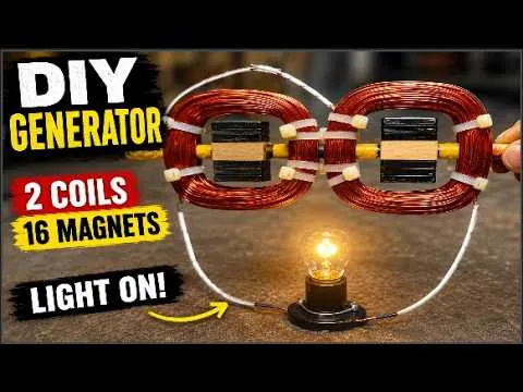
Two coils.
Sixteen magnets.
One working generator.
A beginner build log for turning copper wire, spinning magnets, and a bit of mechanical motion into a lit bulb — the same principle that scales all the way up to the inverter on your wall.
If you're just getting started with hands-on electricity projects, a small magnet-and-coil generator is one of the best ways to actually see electromagnetic induction happen, rather than just read about it. This build keeps the parts list short — two coils, sixteen magnets, a shaft, and some wood — while still producing a real, testable electrical output.
Below is the full sequence, from a one-coil prototype through to a finished, wired, and tested generator.
WATCH THE FULL BUILD
§1 The Build Sequence
-
01
Prototype with one coil first
Rather than assembling the full sixteen-magnet rotor blind, it helps to prove the concept small. The first test setup uses eight BLC wheel magnets — four facing four — and a single coil, enough to confirm the design works before scaling it up.
Wooden spacer pieces, cut to match the exact shape and size of the magnets, sit between them on the rotor. They hold the magnetic assembly firmly in place and keep everything aligned as it spins.
-
02
Build and balance the rotor
Each wooden piece gets a center hole drilled through it so a steel shaft can pass through the middle — this is what lets the whole magnetic assembly rotate smoothly and stay balanced. Even spacing and secure mounting matter here: any looseness shows up as vibration once the rotor is spinning at speed.
For smoother rotation, copper pipe is cut into three equal segments and used as bushings. These keep the shaft aligned, cut down on friction, and give the assembly stable, consistent movement.
-
03
Wind the first coil
With a single coil, the underlying principle is easy to observe directly: as magnets sweep past the stationary coil, the changing magnetic field induces a voltage in the copper winding. That's electromagnetic induction, happening in front of you.
- Cut a wooden coil form to size — keeps the winding neat and consistent.
- Chuck the form into a drill so it spins freely while winding.
- Wind 0.71 mm enamel-coated copper wire to the required turn count.
- Secure the wire ends, then mount the coil onto the generator frame.
-
04
Wind the second coil, identically
The second coil is built the exact same way, using an identical wooden form and the same wire gauge and turn count. Keeping both coils matched matters — mismatched coils mean uneven output between the two.
Mount it onto the frame in the same orientation as the first. Proper alignment between both coils is what gives you a smooth, stable electrical output rather than an uneven or noisy one.
-
05
Wire the coils in series
Connect one wire from the first coil to one wire from the second, joining them in series. The two remaining wires become your output terminals — this is where you'll connect a load and measure voltage during testing.
§2 Parts & Spec Sheet
Everything used in this build, at a glance.
| Component | Detail |
|---|---|
| Magnets | 16 × BLC wheel magnets (8 per coil station) |
| Coils | 2, wound identically, series-connected |
| Wire | 0.71 mm enamel-coated copper |
| Rotor spacers | Wood, cut to magnet profile |
| Shaft | Steel, center-mounted |
| Bushings | Copper pipe, cut into 3 equal segments |
| Coil forms | Wood, matched pair |
| Drive | Hand drill (test rig) |
| Test load | Incandescent bulb |
§3 Testing the Generator
To test the build, connect a small light bulb across the two output wires. Spin the shaft at a steady speed with a drill. As the magnets rotate past the coils, the generator starts producing electricity, and the bulb lights up once the rotor reaches sufficient speed. A brighter bulb means more power is being generated — a simple, direct way to confirm the generator is actually working.
This is a demonstration project, not a power source
- Wear appropriate safety equipment when handling magnets, power tools, and rotating parts.
- Perform assembly and testing in a controlled, well-ventilated space.
- Strong magnets can pinch skin or damage nearby electronics — keep them clear of pacemakers, credit cards, and sensitive devices.
- Beginners should not attempt this without proper guidance or supervision.
§4 Why Start This Small
Scaling up from a single coil and eight magnets to a full two-coil, sixteen-magnet generator is a natural next step once the basic principle is proven. It's an inexpensive, low-tech way to understand how mechanical motion — from a hand crank, a drill, or eventually a small turbine — gets converted into usable electrical energy. It's the same core principle behind much larger generators, and behind the inverter systems that turn that energy into something your home can actually use.
§5 Frequently Asked Questions
Common questions that come up when building this generator, gathered in one place.
01Do I need exactly 16 magnets, or can I use more or fewer?+
Sixteen keeps the math simple and the rotor easy to balance for a two-coil design, but the count isn't magic. More magnets generally mean more induced pulses per rotation and a smoother output, while fewer make the build simpler but choppier. Just keep the count even and evenly spaced so the poles alternate correctly around the rotor.
02Can I substitute a different wire gauge for the 0.71 mm copper wire?+
Yes, within reason. Thinner wire lets you fit more turns in the same coil form, which raises voltage but increases resistance and lowers current capacity. Thicker wire does the opposite. 0.71 mm is a practical middle ground for a beginner build — if you swap gauges, expect your turn count and output to shift accordingly.
03How many turns should each coil actually have?+
There's no single correct number — it depends on your wire gauge, coil form size, and target voltage. More turns raise the induced voltage but also add resistance and weight. A common approach is to wind in batches, test the output, and stop once you're hitting a voltage that's useful for your load.
04Why do the two coils need to be identical?+
Mismatched coils produce mismatched voltage and phase behavior, which shows up as an uneven or noisy combined output once they're wired in series. Matching the wire gauge, turn count, and winding direction keeps both coils contributing evenly.
05What's the purpose of the wooden spacers between magnets?+
They act as structural filler, holding each magnet firmly in its slot around the rotor and keeping the spacing between magnets consistent. Without them, magnets can shift under the strong attractive and repulsive forces at play, throwing off the balance and the timing of the induced pulses.
06Why use copper pipe for the bushings instead of a bearing?+
Copper bushings are a low-cost, low-tech way to reduce friction and keep the shaft aligned, which is enough for a slow-speed demonstration build. A proper ball bearing would spin more freely and last longer under sustained use, so it's a reasonable upgrade if you plan to run the generator for extended periods.
07Is the output AC or DC?+
AC. As magnets of alternating polarity pass the coil, the induced current reverses direction with each pole change, producing an alternating waveform. To power DC devices, you'd need to add a rectifier — commonly a small bridge rectifier circuit — between the coil output and your load.
08How fast does the shaft need to spin to light the bulb?+
It depends on your specific coil, magnet strength, and turn count, so there's no fixed number. In practice, you spin the shaft with a drill and gradually increase speed until the bulb reaches a noticeable brightness — that's your practical threshold for this build.
09Can I use neodymium magnets instead of BLC wheel magnets?+
Yes, and stronger magnets typically induce a higher voltage at the same rotation speed. Just make sure any substitute magnets are cut or shaped to fit your wooden spacer profile, and handle them carefully — stronger magnets are also more likely to pinch fingers or snap together unexpectedly during assembly.
10What does "cogging" mean, and will this design have it?+
Cogging is the notchy resistance you feel when turning a generator's shaft by hand, caused by magnets snapping toward the coil's iron core (if it has one) as they pass. A coreless coil design like this one, wound on a wooden form with no iron core, largely avoids that effect, giving a smoother, lower-resistance spin.
11Could this generator actually power something useful, like a phone charger?+
Not as built — this design is sized to demonstrate the principle, light a small test bulb, and teach the fundamentals, not to deliver sustained, regulated power. Charging real electronics safely would require rectification, voltage regulation, and a much higher and more consistent power output than a hand-drill test rig can provide.
12Do I need to balance the rotor, or is eyeballing it good enough?+
It's worth taking seriously. An unbalanced rotor vibrates more as speed increases, which stresses the shaft, bushings, and mounting frame, and makes the whole assembly noisier and less efficient. Even spacing of magnets and spacers around the shaft goes a long way toward a smooth spin.
13What happens if I wind the two coils in opposite directions by mistake?+
Wiring two oppositely-wound coils in series can cause their induced voltages to partially or fully cancel out instead of adding together, leaving you with a much weaker output than expected. If your finished generator seems underpowered, mismatched winding direction is one of the first things worth checking.
14Is a drill the only way to spin the shaft, or can I use something else?+
A drill is just a convenient, controllable way to test the build. Once proven, the same rotor could be driven by a hand crank, a bicycle wheel setup, a small water wheel, or any other mechanical input capable of turning the shaft at a reasonably steady speed.
15Is this project safe for a beginner to attempt alone?+
It's approachable, but not entirely hands-off. Spinning magnets, power tools, and exposed wiring all carry real risk if handled carelessly. Wear appropriate safety gear, work in a controlled space, and if you're new to tools or electronics, build it alongside someone with more experience rather than attempting it fully unsupervised.
Discussion
Amazing build! The 16-magnet design looks very efficient, and the craftsmanship is impressive. Thanks for sharing this DIY project!