
Permanent Magnet Generator: How It Works, Types, Efficiency and Applications
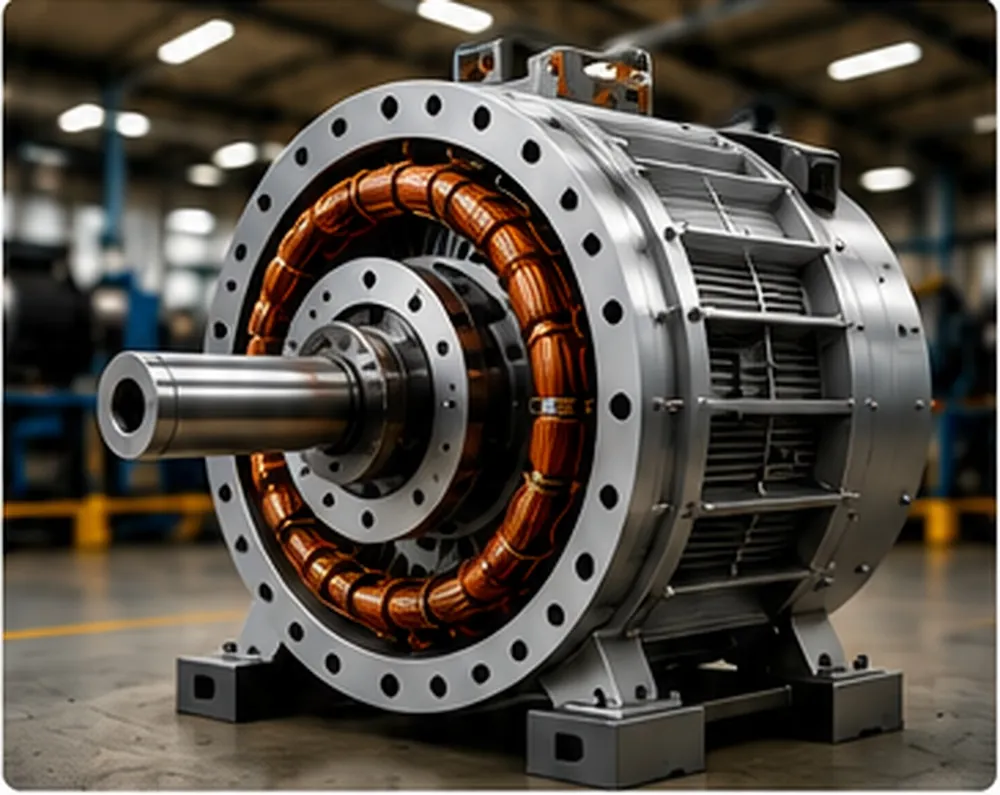
A permanent magnet generator converts mechanical rotation into electrical energy by utilizing fixed permanent magnets rather than electrically excited rotor coils. This engineering architecture eliminates slip rings, reduces internal rotor thermal losses, and enables robust, self-starting power generation across renewable energy systems, off-grid battery banks, and industrial direct-drive prime movers.
Evaluating or designing a power generation setup? Use our free engineering calculators:
What Is a Permanent Magnet Generator?
In traditional power engineering, generating electrical energy requires two primary elements: a magnetic field and an electrical conductor moving relative to that field. In conventional wound-field alternators, the magnetic field is created by passing direct current (DC) through coils of wire wrapped around the rotor. This excitation current must be fed through mechanical slip rings and carbon brushes or generated through an auxiliary brushless exciter system.
A permanent magnet generator completely replaces these electrically excited rotor coils with high-coercivity permanent magnets (such as Neodymium Iron Boron or hard ferrites). By doing so, the machine requires zero external electrical energy to create its internal magnetic field. When a mechanical prime mover—such as a wind turbine rotor, a water turbine runner, an internal combustion engine, or an industrial drive belt—rotates the generator shaft, mechanical work is immediately converted into electrical potential via electromagnetic induction.
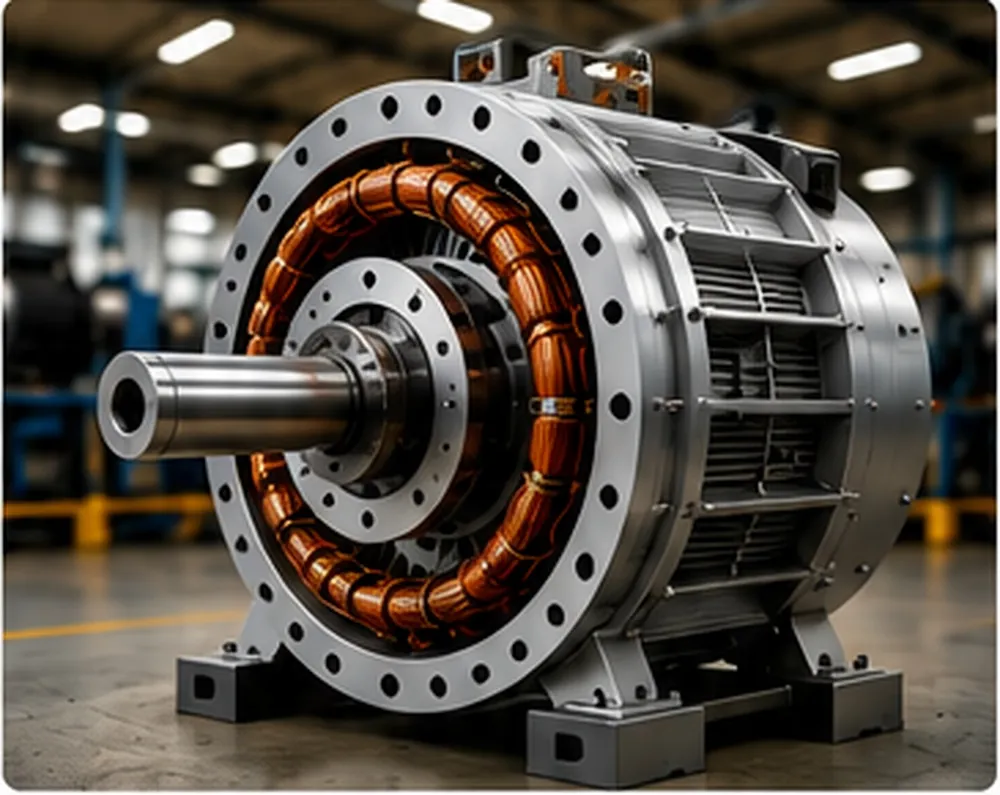
Distinguishing Generators from Motors
While both machines share nearly identical structural topologies based on magnetic flux and copper conductors, their energetic direction differs:
- Electric Motor: Absorbs electrical energy (voltage and current) to produce mechanical rotation and torque.
- Electrical Generator: Absorbs mechanical torque and angular velocity to induce voltage and drive electrical current through an external load.
It is vital to recognize that a permanent magnet generator never creates energy from nothing. It operates strictly within the fundamental laws of thermodynamics: the electrical power delivered at its terminals is entirely derived from the mechanical torque and rotational speed supplied by the prime mover, minus internal thermal and frictional losses.
How Does a Permanent Magnet Generator Work?
The working principle of a permanent magnet generator relies directly on Faraday's Law of Electromagnetic Induction and Lenz's Law. Faraday’s formulation defines that the magnitude of the electromotive force ($\mathcal{E}$) induced in a conductor is proportional to the number of turns ($N$) and the time rate of change of magnetic flux ($\Phi_B$) passing through the coil area:
$$\mathcal{E} = -N \frac{\mathrm{d}\Phi_B}{\mathrm{d}t}$$
In a standard three-phase permanent magnet generator, the stator features three distinct sets of insulated copper windings spaced $120^\circ$ electrically apart. As the North and South magnetic poles of the rotor alternate across the stator teeth, the direction of magnetic flux through each phase winding repeatedly reverses. This creates three smooth, sinusoidal alternating current (AC) waveforms shifted in phase by $120^\circ$.
(Wind, Hydro, Engine)
(AC EMF Induced)
Key Variables Governing Performance
The electrical output profile of a PM generator is governed by several core mechanical and physical parameters:
- Rotational Velocity (RPM): Induced voltage rises proportionally with shaft speed because higher rotational velocity increases the rate of change of magnetic flux ($\mathrm{d}\Phi/\mathrm{d}t$).
- Pole Count ($P$): The total number of magnetic poles determines the electrical output frequency ($f$) for a given mechanical shaft speed ($N_{rpm}$), defined by:
$$f = \frac{P \times N_{rpm}}{120}$$ - Magnetic Flux Density ($B$): Stronger magnets introduce a higher total flux into the magnetic circuit, directly raising the induced voltage per turn without requiring higher physical velocity.
- Stator Winding Configuration: Increasing the series turns per coil increases induced open-circuit voltage, while using thicker wire minimizes internal phase resistance ($R_{phase}$) and improves maximum continuous current carrying capability.
Main Components of a Permanent Magnet Generator
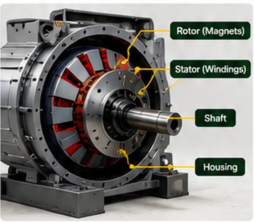
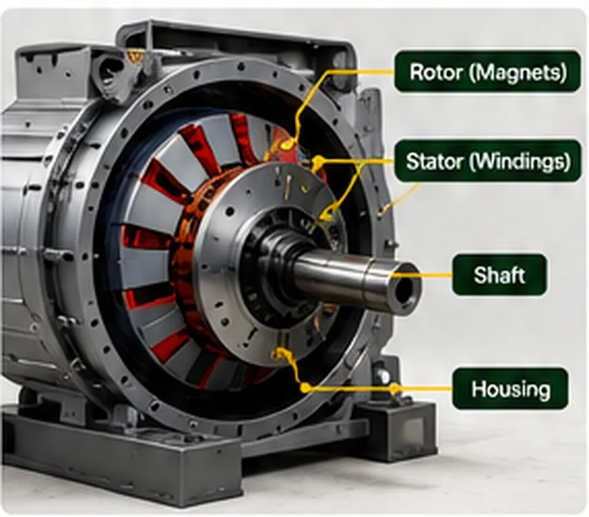
The mechanical architecture of a permanent magnet generator is remarkably elegant compared to wound-rotor or brush-type generators. Because excitation coils and slip rings are unnecessary, mechanical reliability is substantially higher.
| Component | Primary Material | Functional Engineering Role |
|---|---|---|
| Rotor | Structural Steel / Cast Iron / Aluminum | Carries the permanent magnets, maintains mechanical air gap under heavy centrifugal loads, and provides a low-reluctance magnetic return path. |
| Permanent Magnets | NdFeB (Neodymium) or Hard Ferrite / Ceramic | Establishes the constant static magnetic field across the air gap without requiring electrical excitation current. |
| Stator Core | Silicon Steel Laminations (0.35–0.5 mm) | Directs magnetic flux through the phase coils while minimizing parasitic eddy current losses and magnetic hysteresis losses. |
| Stator Windings | Enamelled Magnet Copper Wire (Class H / F) | Conducts induced AC currents; arranged in single-phase or multi-phase star (wye) or delta electrical topologies. |
| Bearings | High-Grade Sealed Deep Groove Ball / Roller | Maintains precise rotor-stator coaxial concentricity and supports axial and radial mechanical shaft loads with minimal friction. |
| Shaft | Hardened Alloy Steel (e.g., 4140 or 1045) | Transmits mechanical torque from prime mover to the rotating magnet assembly. |
| Housing / Enclosure | Cast Aluminum or Ductile Iron (IP55 to IP67) | Protects internal windings and magnets from dust, moisture, and corrosion while providing convective thermal dissipation. |
| Rectifier Bridge | Silicon Diodes / Schottky / MOSFETs | Converts multi-phase raw variable AC output into direct current (DC) for battery charging or inverter input stages. |
| Thermal Cooling | External Cooling Fins / Integral Shaft Fan | Dissipates internal $I^2R$ copper losses and core iron losses to prevent dangerous magnet overheating and thermal demagnetization. |
Magnet Material Selection: Neodymium vs Ferrite
Magnet choice is a critical engineering decision in PM generator construction:
- Neodymium Iron Boron (NdFeB): Offers exceptionally high remanence ($B_r \approx 1.2 - 1.45\,\text{Tesla}$) and high energy product ($BH_{max}$). This allows the generator to be exceptionally compact and lightweight for a given power rating. However, standard grades (e.g., N35, N52) have lower temperature limits and can begin irreversible demagnetization if internal temperatures exceed $80^\circ\text{C}$ to $150^\circ\text{C}$ depending on their coercivity rating (e.g., SH, UH, or EH series).
- Ceramic / Hard Ferrite: Provides lower magnetic flux density ($B_r \approx 0.35 - 0.45\,\text{Tesla}$), requiring substantially larger physical volumes and heavier steel yokes to achieve equal power output. However, ferrites are highly cost-effective, offer outstanding corrosion resistance, and withstand operating temperatures up to $250^\circ\text{C}$ without demagnetizing.
If you are recalculating slot area, wire gauge, and total turns for a custom stator rewinding project, check our Winding Wire Calculator to ensure proper current density and slot fill factor.
Permanent Magnet Generator Types
Permanent magnet generators are categorized according to their magnetic flux path, physical geometry, drive interface, and rotational speed envelope:
1. Permanent Magnet Alternator (PMA)
The term permanent magnet alternator generally refers to compact AC-generating units frequently used in automotive retrofits, light aircraft, marine auxiliary engines, and small micro-wind systems. They are designed to spin at moderate to high speeds and are frequently paired with internal or external three-phase bridge rectifiers to yield stable DC outputs.
2. Permanent Magnet Synchronous Generator (PMSG)
A permanent magnet synchronous generator features an exact lock between mechanical shaft rotational frequency and the electrical frequency of the output voltage. Widely deployed in commercial grid-tied wind turbines and utility-scale hydro systems, PMSGs are praised for their deterministic electrical dynamics and superior power-factor characteristics when combined with active front-end inverters.
3. Axial Flux Permanent Magnet Generator
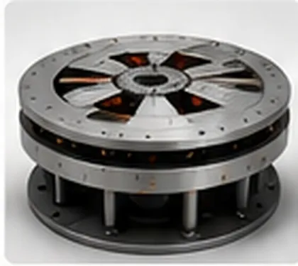
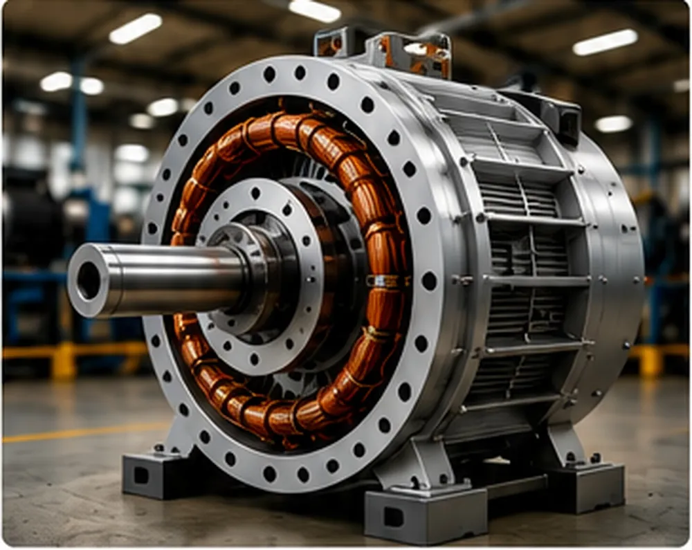
In an axial flux permanent magnet generator, the magnetic flux travels parallel to the rotational shaft axis. The rotor and stator are constructed as flat discs (pancakes) rather than concentric cylinders. This architecture offers a remarkably short axial length, high torque density, and allows multi-rotor configurations (such as a dual-rotor, single-stator "sandwich" layout).
4. Radial Flux Permanent Magnet Generator
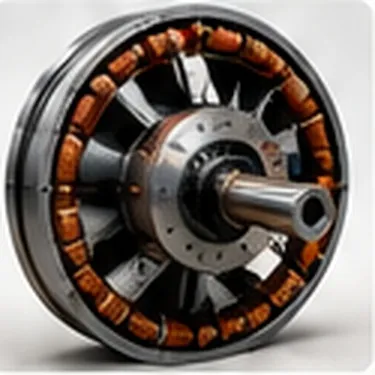
The traditional cylindrical geometry where flux lines pass perpendicular (radially) across the annular air gap between an internal rotating cylindrical magnet assembly and an outer cylindrical stator core. Radial flux machines benefit from decades of mature automated industrial manufacturing processes and simple standard bearing supports.
5. Direct-Drive Permanent Magnet Generator
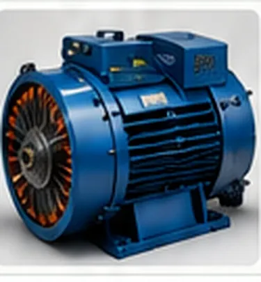
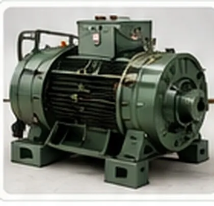
A direct-drive permanent magnet generator is designed to mount directly to low-speed prime movers (such as wind turbine blades or low-head hydro turbines) without requiring an intermediate speed-increasing mechanical gearbox. By engineering a high magnetic pole count (e.g., 24 to 60+ poles) and a large diameter, direct-drive units achieve rated power at 50 to 300 RPM, eliminating gearbox friction, noise, oil maintenance, and mechanical failure risks.
Permanent Magnet Generator vs Conventional Generator
Neither technology is universally superior; each excels in specific engineering applications depending on prime mover stability, speed variability, power scale, and budget.
| Feature / Parameter | Permanent Magnet Generator (PMG) | Conventional Wound-Rotor Generator |
|---|---|---|
| Magnetic Field Source | Permanent Magnets (NdFeB or Ferrite) | Electromagnet (Wound Copper Field Coils) |
| Rotor Excitation Power | Zero external power required | Consumes 1.5% to 5% of total rated power |
| Brushes and Slip Rings | None in the PM rotor excitation system | Often required (or requires complex brushless exciter) |
| Low-Speed Operation | Excellent (Easily scaled with high pole counts) | Poor at low RPM; requires high excitation currents |
| Output Voltage Regulation | Passive (Voltage fluctuates with RPM and load) | Active (Automatic Voltage Regulator adjusts rotor field) |
| Electrical Efficiency | Very High (No rotor copper losses) | Moderate to High (Rotor $I^2R$ thermal losses present) |
| Starting Behavior | Permanent magnetic excitation is available as soon as the rotor turns | Requires residual rotor magnetism or battery flash |
| Capital Cost | Higher initial cost (rare-earth magnet pricing) | Lower raw material cost at large scale |
| Demagnetization Risk | Possible under extreme heat or severe short circuits | None (Magnetic field is fully controllable) |
| Best Suited For | Wind turbines, hydro, mobile off-grid, portable units | Utility fossil plants, diesel backup generators, grid baseload |
If you are evaluating continuous output requirements for your facility or off-grid cabin, verify your total load requirements with our Generator Size Calculator to prevent undersizing your electrical plant.
Permanent Magnet Synchronous Generator
The permanent magnet synchronous generator (PMSG) represents one of the most vital generator categories in modern renewable infrastructure. In a synchronous machine, the mechanical rotation speed of the rotor shaft is precisely matched to the angular velocity of the revolving magnetic field inside the stator.
Unlike induction (asynchronous) generators, which require an external reactive power grid supply and slip (operating slightly above synchronous speed) to generate electrical power, a PMSG generates real power synchronously from the first turn of the rotor shaft without requiring grid magnetizing current.
Variable-Speed Operation and Full-Power Inverters
In modern wind and variable-flow hydro installations, the prime mover rarely operates at a fixed rotational speed. Because wind and water velocities constantly vary, the PMSG generates variable-frequency, variable-voltage AC electricity.
To interface this output with standard 50 Hz or 60 Hz electrical grids or standalone battery banks, a back-to-back full-scale power converter is employed:
- Machine-Side Converter (Rectifier): Converts variable AC from the PMSG into a stable intermediate DC link bus.
- Grid-Side Inverter: Takes the DC bus energy and synthesizes pristine, crystal-locked 50/60 Hz sinusoidal AC voltage matching the amplitude and phase angle of the utility grid or local AC loads.
This decoupled architecture allows the renewable turbine to operate at its maximum aerodynamic or hydrodynamic efficiency (Tip Speed Ratio optimization) across a broad operational speed range.
Axial Flux vs Radial Flux Generators
The magnetic orientation within a generator dramatically shapes its mechanical structure, thermal dissipation capabilities, and manufacturing complexity.
| Design Dimension | Axial Flux Permanent Magnet (AFPM) | Radial Flux Permanent Magnet (RFPM) |
|---|---|---|
| Flux Orientation | Parallel to rotation axis (Axial) | Perpendicular to rotation axis (Radial) |
| Form Factor | Flat disc, pancake-shaped, short axial length | Long cylindrical barrel profile |
| Torque Density | Exceptionally high (larger effective magnet radius) | Standard to high |
| Coreless / Ironless Option | Easily constructed (eliminates cogging torque) | Difficult and structurally complex to implement |
| Mechanical Air Gap Control | Requires rigid thrust bearings against strong axial magnetic attractive forces | Standard radial bearings maintain uniform cylindrical annular air gap easily |
| DIY / Fabrication Ease | High (flat plates and resin casting can be done without specialized stamping dies) | Moderate to difficult (requires precision slotted circular silicon laminations) |
| Thermal Dissipation | Stator often encapsulated; cooling center coils can be challenging | Excellent convective cooling over exterior lamination fins |
Low-RPM Permanent Magnet Generators
Traditional generators are engineered for high-speed operation (typically 1,500 RPM for 4-pole 50 Hz, or 3,600 RPM for 2-pole 60 Hz internal combustion engine pairings). However, natural prime movers such as small wind turbine blades (100–400 RPM) and hydro water wheels rotate at very low speeds.
A low-RPM permanent magnet generator resolves this issue through targeted electromagnetic design:
- High Pole Count: By integrating 16, 24, 36, or more alternating North-South magnet poles around a large-diameter rotor, the rate of magnetic pole reversals past each coil remains high even when the shaft rotates slowly.
- Increased Radius ($r$): Linear tangential velocity ($v = \omega \cdot r$) increases directly with rotor radius. A larger diameter rotor allows the magnets to sweep across the stator coils at high linear speeds despite low angular RPM.
- High Turns per Coil: Dense stator coil turns induce sufficient open-circuit electromotive force to reach battery-charging or grid-inverter voltage thresholds at low rotational speeds.
Permanent Magnet Generator Efficiency
Generator efficiency ($\eta$) is the mathematical ratio between usable electrical power delivered to the load ($P_{out}$) and the mechanical power supplied to the input shaft ($P_{in}$):
$$\eta = \left( \frac{P_{out}}{P_{in}} \right) \times 100\% = \left( \frac{P_{out}}{P_{out} + P_{losses}} \right) \times 100\%$$
Well-engineered permanent magnet generators can achieve very high peak efficiencies, often above 90% in appropriately sized machines, but actual efficiency depends strongly on machine size, speed, load, cooling, winding resistance, and power-electronics losses. Always use the manufacturer’s efficiency curve for system design. This performance advantage stems directly from the elimination of rotor excitation energy losses.
Internal Energy Losses Breakdown
Understanding internal losses is essential for proper thermal sizing and operational efficiency:
- Copper Losses ($I^2R$ Losses): Thermal dissipation within the stator windings caused by electrical resistance ($R$) carrying load current ($I$). These losses rise with the square of the current output.
- Core / Iron Losses ($P_{fe}$): Composed of hysteresis losses (energy required to repeatedly reorient magnetic domains in the steel) and eddy current losses (parasitic circular currents induced in the steel laminations). These scale with magnetic frequency and flux density.
- Mechanical Losses ($P_{mech}$): Friction within the shaft ball bearings and aerodynamic drag (windage) caused by the rotor spinning inside the housing.
- Rectifier Losses ($P_{rect}$): Voltage drop across silicon diodes (typically ~0.7V to 1.1V per diode) in AC-to-DC rectification systems. In low-voltage systems (e.g., 12V or 24V), diode losses can account for 4% to 8% of total power, making active MOSFET synchronous rectification highly beneficial.
Consider a small micro-hydro PM generator operating under test conditions:
• Mechanical shaft input power ($P_{in}$): 2,500 Watts
• Stator copper losses ($I^2R$): 110 Watts
• Stator lamination core losses: 55 Watts
• Bearing friction and windage: 20 Watts
• Three-phase bridge rectifier losses: 45 Watts
• Total internal losses ($P_{losses}$): $110 + 55 + 20 + 45 = \mathbf{230\text{ Watts}}$
• Net electrical power output ($P_{out}$): $2,500 - 230 = \mathbf{2,270\text{ Watts}}$
• Calculated System Efficiency: $(2,270 / 2,500) \times 100\% = \mathbf{90.8\%}$
Voltage and Power Output Characteristics
Unlike utility grid power, which delivers a tightly regulated constant voltage (e.g., 120V or 230V RMS), the open-circuit output voltage ($V_{oc}$) of an unregulated permanent magnet generator is directly proportional to shaft speed:
$$V_{oc} = k_e \times \omega$$
Where $k_e$ represents the generator’s back-EMF voltage constant (in Volts per RPM or Volts per rad/s) and $\omega$ is rotational velocity.
Terminal Voltage Under Electrical Load
When an electrical load is connected, terminal voltage ($V_t$) drops below open-circuit voltage due to internal stator impedance:
$$V_t = V_{oc} - I_{load}(R_s + jX_s)$$
Where $R_s$ is stator winding phase resistance and $X_s$ is synchronous inductive reactance ($\omega L_s$). As shaft speed and output current increase, inductive reactance ($X_s$) grows, causing increased internal voltage drop and limiting maximum peak current output.
To determine proper cabling sizes between the generator terminals, rectifier, and charge controller, consult our Wire Gauge Calculator to prevent excessive resistive voltage drops across long transmission distances.
Permanent Magnet Generators for Wind Turbines
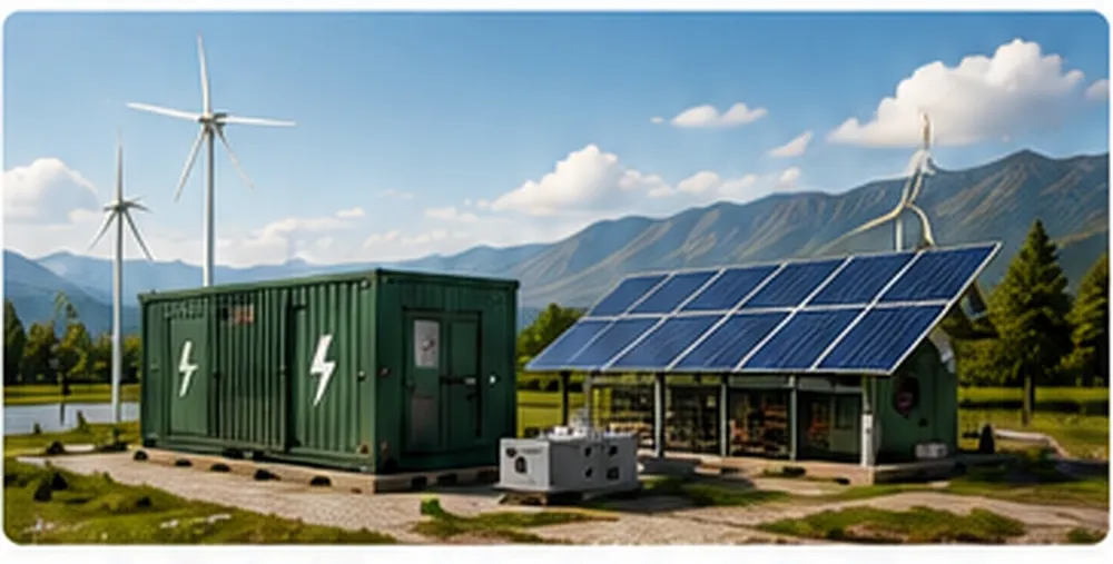
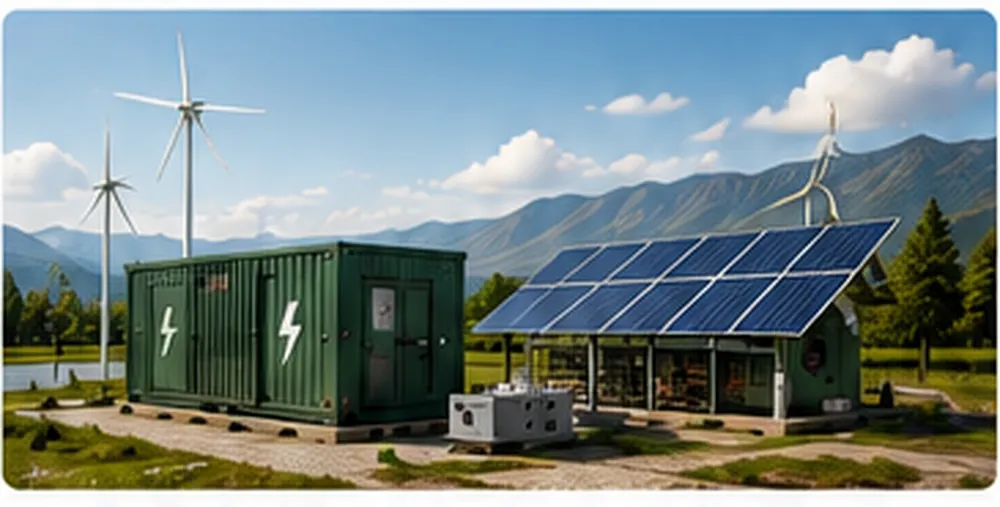
Wind power is one of the most common applications for permanent magnet generators. Because wind speed is stochastic and constantly fluctuating, aerodynamic energy capture requires a generator that operates reliably under wide speed variations.
Direct-Drive Wind Turbine Advantages
- Elimination of Gearbox: The direct-drive configuration mounts the turbine blade hub directly to the PM generator rotor, removing the mechanical gearbox and drastically reducing tower-top maintenance.
- Low Cut-In Speeds: High-flux neodymium designs allow the generator to reach usable charging voltages in light winds.
- Low Cogging Torque: By skewing stator slots or optimizing magnet pole pitch, cogging torque (the magnetic resistance to initial rotation from a standstill) is minimized, allowing turbine blades to start spinning in light breezes.
Permanent Magnet Generators for Hydropower
Micro-hydro and small run-of-the-river installations provide a reliable source of baseload mechanical energy. Water diverted from a stream flows through a penstock pipe, generating dynamic water pressure (head) that drives an impulse turbine (such as a Pelton or Turgo wheel) or a reaction turbine (such as a Francis or Crossflow runner).
Hydro applications present distinct operational conditions compared to wind power:
- Constant Shaft Speed: Under steady penstock flow and head conditions, water turbines spin at a relatively stable RPM, allowing the PM generator to produce consistent voltage and continuous steady-state power output.
- Runaway Speed Protection: If the electrical load is suddenly disconnected (e.g., circuit breaker trip), water turbines can accelerate to 1.8 to 2.2 times their normal operating speed (runaway RPM). The PM generator must be designed mechanically to withstand these high centrifugal forces and electrically to handle the resulting open-circuit overvoltage.
- Continuous 24/7 Duty: Hydro generators operate non-stop for months or years. Industrial-grade bearings, proper grease replenishment pathways, and corrosion-resistant coatings are essential.
Permanent Magnet Generator for Battery Charging
Charging an off-grid battery bank (Lead-Acid, AGM, Gel, or Lithium Iron Phosphate / $\text{LiFePO}_4$) directly with raw power from a permanent magnet generator is not recommended. Because the generator’s raw output is variable-voltage, variable-frequency AC, an intermediate power-conditioning topology is required.
Standard Charging System Architecture
- PMG AC Terminals: Delivers wild 3-phase AC voltage.
- Three-Phase Full-Wave Bridge Rectifier: Converts 3-phase AC into pulsating DC voltage.
- Charge Controller (PWM or MPPT): Steps down fluctuating rectified DC voltage to the precise multi-stage charging profile (Bulk, Absorption, Float) required by the specific battery chemistry.
- Dump Load / Diversion Controller: In wind and hydro systems, when batteries reach 100% state of charge, excess generator energy must be diverted to a resistive heating element (dump load) to prevent turbine overspeeding and battery overcharging.
- Battery Bank: Stores the chemical energy. If you are configuring a battery storage array, estimate your capacity with our Solar Battery Calculator.
- DC-to-AC Inverter: Converts DC battery voltage into clean 120V/230V AC for standard household and commercial electrical appliances.
Permanent Magnet Generator Controllers and Rectifiers
Because the output of a permanent magnet machine cannot be controlled via rotor excitation current, external power electronic devices must manage the generated power:
| Electronic Device | Core Function | Distinguishing Characteristics |
|---|---|---|
| Three-Phase Rectifier | AC to DC Conversion | Uses six high-power diodes to convert wild three-phase AC input into raw DC power. Passive device; does not regulate voltage. |
| MPPT Charge Controller | Impedance Matching & Charging | Continuously tracks Maximum Power Point to match generator impedance to the battery bank, maximizing energy transfer at varying RPMs. |
| Diversion / Dump Controller | Overspeed & Overvoltage Protection | Monitors system voltage and diverts surplus generator power to air or water heating elements when battery bank is fully charged. |
| Power Inverter | DC to AC Conversion | Converts DC bus or battery energy into clean, regulated single-phase or three-phase 50/60 Hz utility-grade alternating current. |
A rectifier converts AC to DC; a charge controller manages battery charging stages; a voltage regulator stabilizes voltage levels; and an inverter converts DC into AC. These components are complementary parts of a complete power generation system.
Permanent Magnet Generator Design Considerations
Engineering a permanent magnet generator requires a balanced approach to electromagnetic, structural, thermal, and mechanical parameters:
- Air Gap Optimization: The physical clearance between the spinning rotor magnets and stationary stator teeth should be as narrow as mechanical tolerances allow (typically 0.8 mm to 1.5 mm). Wider air gaps increase magnetic reluctance, reducing flux density and generator output.
- Slot-Pole Combination & Cogging Mitigation: Selecting an optimal ratio of stator slots to magnetic poles reduces cogging torque. Methods like skewing stator teeth by one slot pitch or beveling magnet edges minimize torque ripple during startup.
- Thermal Budgeting & Magnet Protection: High-grade NdFeB magnets can lose magnetic strength if internal generator temperatures exceed their rated threshold. Housing enclosures must include sufficient convective fins or forced air cooling to dissipate internal heat under full load.
- Structural Rigidity: The magnetic attraction between high-energy neodymium magnets and steel stator laminations can exert hundreds of kilograms of radial or axial force. Stator plates, rotor backplates, and bearing housings must be stiff enough to prevent mechanical deflection and rotor rub.
DIY Permanent Magnet Generator Engineering
Building a custom permanent magnet alternator is a popular project for renewable energy enthusiasts, off-grid builders, and engineering students. The most approachable design for small workshops is the dual-rotor axial flux coreless generator (commonly known as the Hugh Piggott design).
Step-by-Step DIY Build Workflow
- Define Target Requirements: Determine the target cut-in RPM, operating voltage (e.g., 24V or 48V DC nominal), and maximum peak power output.
- Assess Mechanical Input: Calculate available shaft torque and RPM from your prime mover (e.g., hydro runner or wind blades).
- Fabricate Steel Rotor Discs: Cut two circular discs from 10–12 mm mild steel plate to provide structural support and a magnetic return path.
- Mount Permanent Magnets: Secure alternating North and South rare-earth wedge or block magnets around each rotor disc using high-strength epoxy resin.
- Wind Stator Coils: Wind copper magnet wire onto a coil former, keeping turn counts and wire gauge consistent across all phases. Verify conductor dimensions with our Wire Gauge Calculator.
- Cast Stator in Epoxy Resin: Arrange the coils in a 3-phase circular layout and cast them in structural fiberglass resin to create a rigid, coreless stator disk.
- Assemble Mechanical Spindle: Mount the rotors and stator onto an automotive hub spindle, adjusting the air gap with threaded studs.
- Bench Testing: Spin the generator with a lathe or electric motor to measure open-circuit AC voltage across different RPM steps.
- Rectification & Load Testing: Connect a 3-phase bridge rectifier, connect a controlled resistive load, and monitor thermal performance under load.
Large neodymium magnets exert extreme magnetic attractive forces. Keep fingers clear of magnet pinch zones, keep ferrous tools away from open magnet discs, and wear non-magnetic protective gear during assembly.
Key Engineering Advantages
- High Efficiency: The absence of rotor excitation windings eliminates rotor copper losses ($I^2R$), yielding higher operating efficiency than conventional wound-rotor alternators.
- Brushless, Low-Maintenance Design: Eliminating slip rings, brushes, and separate exciters reduces mechanical wear and simplifies ongoing maintenance.
- High Low-Speed Performance: Multi-pole designs generate usable power at low rotational speeds, enabling direct-drive configurations that eliminate mechanical gearboxes.
- Compact Size and Weight: High-flux neodymium magnets provide high power and torque density, reducing overall generator dimensions and weight.
- Instant Self-Excitation: Generates voltage immediately upon rotation without requiring external DC excitation or auxiliary starting batteries.
Disadvantages and Operational Limitations
- Passive Voltage Regulation: Terminal voltage varies directly with shaft speed and electrical load, requiring external power electronics for tight regulation.
- Risk of Thermal Demagnetization: Excessive operating temperatures or severe electrical short circuits can cause permanent magnetic strength loss.
- Material Costs: High-energy rare-earth magnets (Neodymium, Dysprosium) represent a significant portion of total manufacturing cost and are subject to market price volatility.
- Challenging Mechanical Assembly: Strong internal magnetic forces complicate manufacturing, assembly, bearing alignment, and field maintenance.
- Sustained Short-Circuit Fault Currents: Because the magnetic field cannot be switched off via an excitation circuit, an internal short circuit will continue generating heat as long as the prime mover turns the shaft.
Maintenance and Long-Term Reliability
While permanent magnet generators are mechanically simple and reliable, regular preventative maintenance ensures long service life:
- Bearing Service: Inspect, lubricate, and replace rotor shaft bearings according to run-time intervals. Bearing failure can cause the rotor to contact the stator, leading to severe mechanical damage.
- Vibration Analysis: Regularly check for shaft misalignment, aerodynamic imbalance, or structural looseness to prevent fatigue failures.
- Winding Insulation Resistance: Test stator winding insulation resistance using a megohmmeter (insulation resistance tester) to check for moisture ingress or insulation aging.
- Corrosion Control: Inspect housings, cable glands, and shaft seals in marine or coastal environments to protect magnets from oxidation.
- Thermal Inspections: Use an infrared thermometer or thermal camera to detect localized hotspots caused by unbalanced phase loading or loose electrical connections.
Troubleshooting Common Faults
| Observed Symptom | Possible Root Cause | Recommended Diagnostic Action |
|---|---|---|
| Zero or Extremely Low Output Voltage |
• Insufficient prime mover RPM • Blown diodes in 3-phase rectifier • Open circuit in stator winding • Complete thermal demagnetization |
1. Measure shaft RPM with a digital tachometer. 2. Test rectifier diodes with a multimeter diode mode. 3. Check stator phase-to-phase continuity and resistance. 4. Measure open-circuit AC voltage at a calibrated test RPM. |
| Severe Output Voltage Fluctuation |
• Unstable prime mover speed/torque • Intermittent electrical connection • Faulty charge controller switching |
1. Check mechanical drive belts, couplings, or blades for slippage. 2. Torque all high-current terminal connections. 3. Test charge controller on a stable DC bench supply. |
| Excessive Internal Generator Heat |
• Sustained electrical overload • Blocked cooling airflow fins • Shorted turns inside stator coil • Bearing failure |
1. Verify load current with a true-RMS clamp meter. 2. Clean housing cooling channels and fans. 3. Measure phase resistances for balance. 4. Rotate shaft by hand; listen for bearing roughness. |
| Excessive Acoustic Noise and Vibration |
• Mechanical shaft misalignment • Unbalanced 3-phase electrical load • Rotor-stator physical contact (rub) • Severe cogging torque resonance |
1. Check shaft runout using a dial indicator gauge. 2. Verify balanced current draw across all three phases. 3. Inspect internal air gap for rubbing marks. 4. Ensure structural mounting frame is sufficiently rigid. |
Crucial Safety Considerations
Permanent magnet generators present specific hazards that differ from conventional electrical machinery:
- Live Terminals Whenever Turning: As long as the rotor shaft is spinning, voltage is present at the generator terminals. The magnetic field cannot be switched off via an excitation breaker. Treat all output conductors as energized whenever the machine is turning.
- Dangerous Open-Circuit Overvoltage: Under disconnected-load or runaway conditions, the open-circuit voltage of a high-speed PM generator can rise to several hundred volts, posing severe electrical shock hazards.
- High Magnetic Pinch Hazards: Disassembled rotors and bare neodymium magnets can pull toward ferrous objects with hundreds of pounds of force. Use non-magnetic tools and keep hands clear of magnet pinch points.
- High Short-Circuit Energy: Off-grid battery banks can deliver thousands of amperes into a fault. Always install properly rated DC fuses or circuit breakers directly adjacent to battery terminals.
Permanent Magnet Generator Buying Guide
When purchasing a permanent magnet generator for a renewable energy installation or industrial application, look beyond nominal nameplate wattage and evaluate these key technical specifications:
- Rated RPM vs Actual Available RPM: Ensure the generator reaches its rated output voltage at the shaft speed your prime mover can realistically supply. A "2,000 Watt" generator rated at 3,000 RPM will produce only a fraction of that power if driven by a 300 RPM water wheel without speed gearing.
- Continuous Duty vs Peak Rating: Look for continuous duty ratings (IEC Duty Cycle S1). Avoid units that list short-term surge or peak power capabilities as their primary headline rating.
- Voltage Constant ($K_e$) and Operating Voltage: Match the generator’s output voltage curve to your system design (e.g., 12V, 24V, 48V DC battery bank, or 300V+ for grid-tie string inverters).
- Environmental Protection Rating: Outdoor wind and hydro installations should use an enclosure IP rating appropriate to the site’s dust, water, immersion, and corrosion exposure; IP65 or higher may be appropriate for many exposed installations, but the final rating should follow the equipment and site requirements.
- Shaft and Bearing Construction: Ensure the drive shaft diameter, keyway dimensions, and bearing ratings can support the radial and thrust loads exerted by your turbine blades or drive pulleys.
Planning a Generator or Renewable Power System?
Sizing a reliable power generation system requires matching your mechanical prime mover, electrical generator, transmission cabling, charge controller, battery bank, and inverter. Explore our suite of engineering calculators to plan your project with confidence:
Frequently Asked Questions
What is a permanent magnet generator?
A permanent magnet generator (PMG) is an electromechanical device that converts mechanical energy into electrical energy using permanent magnets to establish the excitation field, rather than relying on electrically powered field coils.
How does a permanent magnet generator work?
It operates on Faraday's law of electromagnetic induction. As a prime mover turns the rotor, the permanent magnets create a moving magnetic field across the stationary stator coils. This changing magnetic flux induces an alternating electromotive force (EMF) in the windings, generating AC power.
What is a permanent magnet alternator?
A permanent magnet alternator (PMA) is a type of PM generator that inherently produces alternating current (AC). The term is commonly used in automotive, marine, and small wind turbine contexts where the raw AC output is subsequently rectified to DC.
What is a permanent magnet synchronous generator?
A permanent magnet synchronous generator (PMSG) is a generator where the electrical frequency of the generated voltage is directly synchronized with the mechanical rotational speed of the rotor and the number of magnetic pole pairs.
Are permanent magnet generators more efficient?
They often exhibit higher electrical efficiency than conventional wound-rotor machines because they eliminate rotor copper losses and excitation power requirements, although efficiency varies across different speed and loading conditions.
Can a permanent magnet generator work at low RPM?
Yes. When constructed with a high number of magnetic poles and suitable stator geometry, low-RPM permanent magnet generators can produce usable voltage directly at low mechanical speeds, often eliminating the need for a mechanical gearbox.
What affects permanent magnet generator voltage?
Output voltage is primarily governed by rotational speed (RPM), magnetic flux density of the magnets, number of series turns in the stator coils, stator geometry, air gap width, and the connected electrical load.
Can a permanent magnet generator charge a battery?
Yes, provided the alternating current (AC) output is converted to direct current (DC) via a rectifier and regulated through a compatible charge controller to match the safe charging profile and voltage limits of the battery bank.
Does a permanent magnet generator produce AC or DC?
Inherently, all permanent magnet generators produce alternating current (AC) within their stator windings because the magnetic poles alternating between North and South sweep past the coils. DC output is achieved through internal or external rectification.
What does a rectifier do in a permanent magnet generator system?
A rectifier uses diodes or active semiconductors to convert the variable-frequency, variable-voltage AC output generated by the PM generator into direct current (DC) suitable for battery charging or DC bus inputs.
Can a permanent magnet generator be used for wind power?
Yes, PM generators and PMSGs are widely used in wind turbines. Their ability to deliver high torque at low speeds makes them ideal for direct-drive wind systems, reducing maintenance by eliminating gearboxes.
Can it be used for hydropower?
Yes. In micro-hydro and small hydro installations, PM generators efficiently convert the continuous mechanical torque from Pelton, Turgo, or Francis turbines into steady electrical power.
What is an axial flux permanent magnet generator?
An axial flux generator is a machine where the magnetic flux travels parallel to the axis of shaft rotation across disc-shaped rotors and stators, resulting in a compact, flat, pancake-style profile.
What is a radial flux permanent magnet generator?
A radial flux generator is the traditional cylindrical design where magnetic flux flows perpendicular (radially) to the rotating shaft across a cylindrical air gap between the outer stator and inner rotor.
What is the difference between a permanent magnet generator and a conventional alternator?
A conventional alternator uses an electromagnet powered by DC excitation current through brushes and slip rings to create the rotor field, allowing active voltage control, while a PM generator uses fixed permanent magnets without brushes.
How long do permanent magnet generators last?
With proper bearing lubrication, thermal management, and corrosion protection, modern PM generators can operate reliably for 15 to 25 years or more, as modern rare-earth magnets lose less than 1% of their magnetic strength per decade under normal conditions.
Can permanent magnet generators overheat?
Yes. Sustained electrical overload, poor ventilation, or elevated ambient temperatures can cause high winding heat, which risks insulation breakdown and permanent thermal demagnetization of the magnets.
What RPM is needed for a permanent magnet generator?
There is no single required RPM. High-speed models may require 1,500 to 3,600 RPM, whereas multi-pole low-speed direct-drive models are engineered to generate full rated output at 100 to 500 RPM.
Can you build a permanent magnet generator yourself?
Yes, many DIY renewable energy enthusiasts build axial flux or radial flux PM generators using magnet discs, resin-cast stator coils, and steel backplates, though precise mechanical balancing and electrical safety must be observed.
What should I consider before buying one?
Key factors include rated power at your available prime mover RPM, operating voltage curve, phase configuration (single vs three-phase), continuous duty thermal rating, IP environmental enclosure rating, and compatibility with your rectifier or charge controller.
Final Takeaway
The permanent magnet generator has established itself as an essential component in modern renewable energy engineering, off-grid power systems, and high-efficiency electromechanical designs. By replacing traditional rotor field coils, slip rings, and brush assemblies with high-coercivity permanent magnets, PM generators offer high electrical efficiency, simplified mechanics, and strong low-RPM power generation capabilities.
Whether you are deploying a direct-drive wind turbine nacelle, installing a run-of-the-river micro-hydro plant, or fabricating a custom DIY alternator, matching the generator's electromagnetic design to your prime mover's speed and torque curve is crucial for reliable performance. Sizing the machine correctly, managing operating temperatures, and selecting compatible rectifiers and charge controllers ensures safe, efficient, and dependable power generation across years of continuous service.
For more engineering guides, technical tools, and calculation resources for inverters, battery storage banks, solar systems, and power generators, explore our technical library at Inverter110.com.