
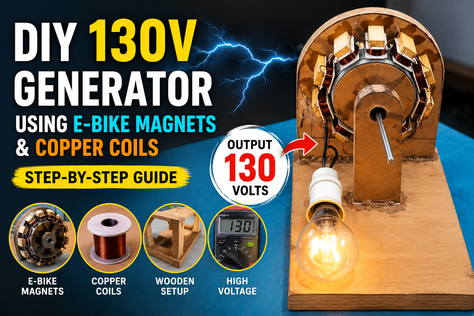
How a DIY Wooden Generator Produces 130 Volts Using E-Bike Magnets and Copper Coils
A homemade electricity generator may sound like a complicated engineering project, but with the right materials and careful assembly, it becomes an impressive demonstration of practical physics and mechanical design. In this project, a creator transforms simple materials—wood, copper wire, PVC tubing, bearings, and electric bike hub motor magnets—into a fully functional generator capable of producing up to 130 volts of electricity.
The entire setup works by converting rotational energy into electrical energy through electromagnetic induction. By rotating powerful magnets around carefully wound copper coils, the system generates usable electrical power strong enough to light bulbs and demonstrate real voltage output. The project not only showcases creativity and engineering skill but also helps viewers understand the basic principles behind electricity generation used in power plants and commercial generators worldwide.
Below is a detailed breakdown of how the DIY generator was constructed, how it works, and why each component plays a critical role in achieving high-voltage output.
Building the Wooden Rotor and Generator Frame
The foundation of the project begins with the magnet rotor taken from an electric bike hub motor. E-bike hub motors contain strong permanent magnets that are ideal for homemade generator systems because they create powerful magnetic fields during rotation. The builder first removes the rotor assembly and measures it carefully before cutting several wooden pieces to form the generator’s support frame.
Accuracy is essential during this stage. Every wooden piece must be cut precisely so the rotor remains balanced while spinning at high speed. Poor alignment or uneven spacing could create vibration, friction, or unstable rotation, reducing efficiency and potentially damaging the setup. The wooden sections are glued together to create a solid structural base that supports both the rotating magnet assembly and the stationary coil section.
Once assembled, the wooden rotor is mounted onto a lathe machine. The lathe is used to smooth and shape the wood so it perfectly matches the dimensions of the magnet rotor. This step is critical because the magnets must sit evenly around the rotor without gaps or imbalance. A smooth cylindrical surface also helps reduce vibration during operation and improves rotational stability at high speeds.
After shaping the rotor, a hole is drilled through its center to install the shaft. The shaft acts as the spinning axle of the generator, allowing the rotor to rotate smoothly while remaining centered. Proper shaft alignment is extremely important because even slight misalignment can reduce performance and create unnecessary friction. Once installed securely, the shaft becomes the core rotating component of the entire generator system.
The magnets are then removed carefully from the original electric bike rotor and attached evenly around the wooden rotor. Proper spacing between the magnets ensures consis
tent magnetic interaction with the copper coils during rotation. This magnetic arrangement becomes the heart of the electricity generation process. As the rotor spins, the moving magnetic fields pass across nearby coils and induce electrical curr
went.
This entire phase highlights one of the most important lessons in IY engineering: precision matters. Balanced construction, smooth rotation, and accurate alignment directly affect the generator’s efficiency, voltage output, and operational stability.
Creating the Coil Bobbins and Copper Windings
After completing the rotor assembly, the next major step involves constructing the copper wire coils responsible for generating electricity. The builder cuts ten small wooden pieces slightly smaller than the magnets themselves. These wooden sections serve as side supports for the coil bobbins.
In addition to the wooden supports, twenty PVC pieces are cut to specific dimensions. These PVC sections form the main body structure of the bobbins and provide space for winding the copper wire coils evenly. Accurate sizing is again extremely important because all bobbins must remain identical to ensure balanced electrical generation across the system.
The wooden and PVC components are assembled together to create ten separate bobbins, each designed to hold one copper wire coil. Every bobbin must be strong and stable enough to maintain coil shape during operation. Properly constructed bobbins improve wire organization, magnetic interaction, and overall generator efficiency.
To begin winding the coils, a hole is drilled through the center of each bobbin. A screw is then used to mount the bobbin inside a drill machine, allowing it to rotate smoothly during the winding process. This simple but effective method makes it easier to wrap the copper wire tightly and evenly.
The builder uses copper wire with a thickness of 0.315 mm and winds it carefully around each bobbin. Tight and evenly layered winding is essential because neat coils improve magnetic induction and electrical output. Loose or uneven windings could reduce performance and create inconsistent voltage generation.
Each coil is wound with the same number of turns to ensure equal resistance and balanced electrical behavior. Consistency between coils is one of the most important principles in generator construction because unequal coils can cause unstable output and reduced efficiency.
These completed coils later become stationary components positioned around the spinning magnet rotor. As the magnets rotate past the coils, changing magnetic fields induce electrical current within the copper wire. This process, known as electromagnetic induction, forms the scientific basis of nearly all modern electricity generation systems.
The coil-building phase demonstrates how relatively simple materials can be transformed into highly functional electrical components through careful craftsmanship and attention to detail.
Assembling the Generator and Connecting the Electrical System
Once the rotor and coils are prepared, the project moves into final assembly. A new wooden board is used as the mounting platform for the rotor and coil system. The rotor is first fixed carefully onto the wooden support, and the exact positions for all ten coils are marked around it.
These markings ensure proper spacing between the rotating magnets and stationary coils. Correct alignment is essential because the magnets must pass smoothly in front of each coil during rotation. If spacing is inconsistent, the magnetic interaction becomes uneven, reducing voltage output and system stability.
After marking the positions, the wooden base is cut and shaped according to the required design. The board functions as the structural support for the coils and helps maintain accurate positioning during operation. A stable mounting platform is especially important when the generator spins at high speed.
The coils are then fixed onto the wooden plate one by one. Each coil is placed after a magnet position with proper spacing and alignment. Secure mounting prevents movement during rotation and ensures consistent magnetic interaction. This careful arrangement significantly improves voltage generation efficiency and smooth system performance.
Next comes the electrical wiring stage. The builder connects the coils in series by linking the output wire of one coil to the input wire of the next. Series connection allows the voltages generated by individual coils to combine together, resulting in much higher total output voltage.
The first and last wires are left free as the generator’s final output terminals. Proper insulation and secure wire connections are essential for safe operation and efficient electricity flow. Poor wiring could cause voltage loss, unstable output, or electrical hazards.
To complete the structure, the coil assembly is mounted onto a strong wooden base plate. Another wooden support containing a bearing is installed to support the rotating shaft. The bearing reduces friction, improves rotational smoothness, and helps maintain balance during operation.
At this stage, the DIY generator is fully assembled and ready for testing. The combination of a balanced rotor, strong magnets, evenly wound coils, and smooth bearings creates a surprisingly effective homemade electricity generation system.
Testing the Generator and Achieving 130 Volts
With construction complete, the creator begins testing the generator’s electrical output using a voltmeter connected to the output terminals. The first test involves spinning the rotor by hand. Even at low speed, the generator successfully produces around 27 volts, proving that the electromagnetic system is functioning correctly.
The next test increases rotational speed using a rope mechanism. Faster rotation causes the magnets to pass the coils more quickly, increasing the rate of magnetic field change and generating higher voltage. During this test, the generator reaches approximately 107 volts.
To demonstrate practical usability, a light bulb is connected to the generator output. As the rotor spins, the bulb glows successfully, confirming that the system can produce real electrical power capable of driving an electrical load.
For maximum performance testing, the creator uses a drill machine to spin the generator at much higher speed. The increased rotational energy dramatically boosts voltage generation, allowing the system to achieve approximately 130 volts.
This result highlights an important principle of generator physics: higher rotational speed increases magnetic movement across the coils, which in turn increases electrical output. Faster spinning means more rapid magnetic field changes, resulting in stronger induced current and higher voltage production.
To further test the generator’s capabilities, two light bulbs are connected simultaneously. The generator successfully powers both bulbs while spinning under load, proving the system’s efficiency and demonstrating that the homemade setup can handle real electrical demand.
The project concludes with important safety warnings. Since the generator produces high-voltage electricity, users are advised to avoid touching exposed wires and always use proper protective equipment. High-voltage systems can be dangerous if handled incorrectly, especially in homemade experimental setups.
Overall, this DIY wooden generator project serves as an excellent educational example of electromagnetic induction, mechanical engineering, and creative problem-solving. Using affordable materials and simple construction techniques, the builder demonstrates how rotational motion can be transformed into usable electrical energy. Beyond being an impressive homemade invention, the project also provides valuable insight into the same scientific principles used in commercial power generation systems around the world.

Frequently Asked Questions (FAQs)
| Question | Answer |
|---|---|
| How does the DIY wooden generator work? | The generator works by rotating powerful magnets around copper wire coils. This movement creates electromagnetic induction, which generates electricity. |
| What materials are required for this generator project? | The project uses e-bike magnets, copper wire, wooden boards, PVC pipes, bearings, a shaft, screws, and glue. |
| Why are electric bike magnets used? | E-bike hub motor magnets are strong permanent magnets that create a powerful magnetic field, making them ideal for generating electricity efficiently. |
| How many coils are used in the generator? | The generator uses 10 copper wire coils arranged around the rotating magnet rotor. |
| What type of copper wire is used for the coils? | The builder uses 0.315 mm copper wire for winding the coils evenly and tightly. |
| Why is proper coil alignment important? | Proper alignment ensures smooth magnetic interaction between the magnets and coils, which improves voltage output and generator efficiency. |
| How much voltage can this homemade generator produce? | The generator produces around 27 volts by hand spinning and up to 130 volts when rotated at higher speed using a drill machine. |
| Why are the coils connected in series? | Series connection combines the voltage generated by each coil, allowing the generator to produce higher overall output voltage. |
| Can this DIY generator power electrical devices? | Yes. The project successfully powers light bulbs, proving it can generate real usable electrical energy. |
| Is it safe to build and test this generator at home? | Safety precautions are very important because the generator produces high voltage electricity. Avoid touching exposed wires and always use protective equipment during testing. |
Discussion
No comments yet. Be the first to join the conversation!