
How to Make a Free Energy Device at Home Using 2 Magnets and 24 Copper Coils
1. Introduction
In a world driven by the need for sustainable and affordable energy sources, the concept of “free energy” continues to fascinate inventors, hobbyists, and eco-enthusiasts. While the term often sparks debate among scientists due to the laws of thermodynamics, there are indeed ways to harness ambient energy using simple materials. This guide will walk you through building a basic free energy device at home using just two strong magnets and 24 copper coils. This device won’t power your entire home but can be a fantastic learning project or provide supplemental power for small applications.
Free energy devices rely on the principle of electromagnetic induction—a process discovered in the 19th century and still used in modern electricity generation. By moving magnets relative to coils of copper wire, you can generate electricity. The setup described here captures this effect in a small-scale, DIY-friendly way.
2. Understanding Free Energy Concepts
Free energy doesn’t mean energy from nothing—it refers to capturing energy that’s already present in the environment, such as magnetic fields or motion. The most viable free energy systems are based on magnetic induction or harvesting ambient sources (like heat or vibration). In this article, we focus on magnetic induction.
The basic principle is Faraday’s Law of Electromagnetic Induction. It states that a changing magnetic field within a coil of wire induces a voltage across the wire. The faster the magnetic field changes, the greater the induced voltage. This is the foundation of electric generators, including this free energy device.
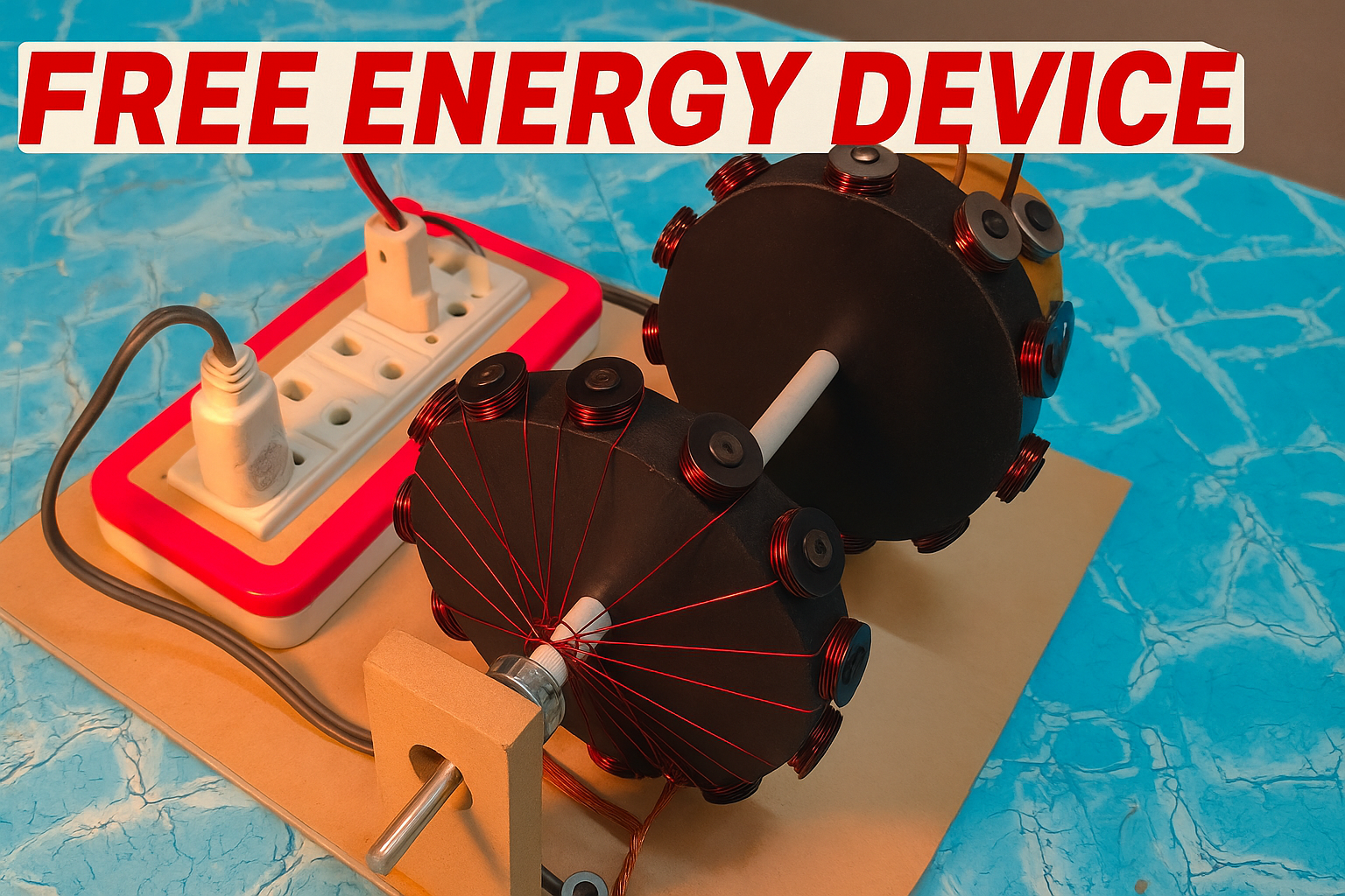
Using neodymium magnets and copper wire, you can create a miniature generator. The setup doesn’t create energy from nothing—it transforms mechanical motion (you or another rotating source spinning a rotor) into electrical energy via magnetic interaction.
The goal is to maximize this interaction through strategic placement of coils and magnets, using a layout that ensures constant movement across the magnetic field lines.
3. The Science Behind Magnetic Induction
Michael Faraday’s experiments in the 1830s laid the groundwork for all modern electric power generation. He discovered that when a magnet moves through a coil of wire, it creates a voltage. If this coil is connected to a circuit, current flows. The greater the number of coils and the faster the magnet moves, the more electricity is produced.
This is due to the creation of an electromotive force (EMF). In our project, the rotor with attached magnets moves across 24 stationary copper coils, generating alternating current (AC) due to the changing magnetic polarity.
When a north pole of a magnet enters a coil, it pushes electrons one way. When the south pole enters, it pushes them the opposite way. This change in direction causes AC, which can be converted to direct current (DC) using a rectifier.
Important factors in maximizing output:
- Number of turns in each copper coil
- Strength of magnets (neodymium is best)
- Speed of rotation
- Distance between magnets and coils
 4. Materials Needed
To build this device, you’ll need:
- 2 Neodymium Magnets (N52 grade) – Strong and capable of generating high magnetic flux
- 24 Copper Coils – Use 22–26 AWG enameled copper wire; about 100–200 turns each
- Non-conductive base – A piece of plastic, acrylic, or wood for mounting
- Rotor Shaft or Disk – Can be plastic or wood; must be balanced for smooth rotation
- Epoxy Glue – For securing components
- Multimeter – To measure voltage output
- Bridge Rectifier – 4 diodes or a ready-made unit
- Capacitor (optional) – For smoothing voltage output
- Voltage Regulator Module (optional) – For consistent DC output
- Battery (optional) – For energy storage
- Small Motor or Manual Crank – To rotate the rotor
5. Safety Precautions
Before beginning, keep in mind:
- Magnet Safety: Neodymium magnets are extremely strong. Keep fingers away when snapping them into place.
- Spinning Components: Ensure the rotor is balanced to avoid wobbling or injury.
- Electrical Precautions: Even low-voltage setups can cause shocks if mishandled.
- Heat: Coils can heat up during prolonged use. Avoid touching them after extended testing.
- Sharp Tools: Use goggles and gloves when handling wires, blades, or soldering tools.
6. Step-by-Step Building Instructions
- Create the Rotor:
- Cut a circular disk and attach the two magnets opposite each other.
- Use epoxy to ensure they’re securely mounted.
- Make sure the poles alternate facing outward (one north, one south).
- Prepare the Base:
- Arrange the 24 copper coils in a circular pattern on a flat base.
- Ensure spacing allows each coil to align with the rotating magnets.
- Winding the Coils:
- Use a spool to wind about 150 turns of copper wire per coil.
- Keep the coils consistent in size and tightness.
- Positioning:
- Mount the rotor so it can spin just above the coils, with a 2–3 mm air gap.
- Use a small bearing or axle to support smooth motion.
- Wiring:
- Connect coils in series for higher voltage, or parallel for more current.
- Use a bridge rectifier to convert AC output to DC.
- Testing:
- Spin the rotor manually or with a small motor.
- Use a multimeter to measure output voltage.
- Output Regulation:
- Add a capacitor to smooth fluctuations.
- Use a voltage regulator to cap output to 5V or 12V.
- Power Storage (Optional):
- Connect the output to a small rechargeable battery for later use.
7. Coil Winding Techniques
Winding your coils properly can dramatically increase performance.
- Use a coil-winding jig to speed up the process and keep consistency.
- Wrap each coil tightly and evenly.
- Insulate the ends before connecting to prevent short circuits.
- Ensure all coils are wound in the same direction unless designed otherwise.
- Label start and end points clearly to simplify wiring.
The number of turns determines voltage: more turns = more voltage.
8. Magnetic Placement Optimization
Strategic placement of magnets boosts energy output:
- Keep magnets as close to the coils as possible without contact.
- Use alternating poles for balanced induction.
- Test positioning using a Gauss meter or multimeter output feedback.
- Balance the rotor to reduce friction and energy waste.
- Increase RPM by manual crank or fan blades to improve generation.
9. Wiring and Output Regulation
- Connect coil ends to a full-wave bridge rectifier (4 diodes in a diamond pattern).
- Add a capacitor after the rectifier to stabilize voltage.
- Use a DC voltage regulator module to set consistent output for USB or LED usage.
- Ensure your wires are rated for the current generated.
- Test with a multimeter before connecting any load.
10. Troubleshooting Common Issues
- No Output: Check coil connections, test polarity, ensure rotor spins properly.
- Low Voltage: Increase the number of turns per coil or spin rotor faster.
- Overheating: Reduce load or improve insulation.
- Inconsistent Output: Add smoothing capacitor or re-check magnet alignment.
- Wobbling Rotor: Rebalance disk or reposition shaft.
11. Power Output and Usage
Don’t expect to run a refrigerator, but this device can power:
- Small LED strips
- USB-powered fans
- Night lights
- Mobile chargers (if regulated)
- Recharge small batteries (AA, 18650)
Voltage output can range from 1V to 15V depending on spin speed and coil count.
12. Limitations and Myths
This is not a perpetual motion machine. The term “free energy” is often misunderstood.
Limitations include:
- Dependence on manual or external motion
- Energy losses from heat and friction
- Material degradation over time
Debunking myths:
- No machine produces energy from nothing
- This device transforms motion into electricity, not magic
- Efficiency can be improved, not made infinite
13. Realistic Applications at Home
This DIY project can be used for:
- Educational demonstrations
- Emergency lighting
- Solar-assisted battery charging
- Remote sensor power
- Hobby electronics
Integrate it with wind or pedal power for more continuous use.
14. Legal and Ethical Considerations
- Don’t connect directly to your home’s power grid
- Only use for personal, experimental, or non-commercial applications unless certified
- Be transparent if you share or sell the idea—don’t make exaggerated claims
15. Conclusion
Building a free energy device with 2 magnets and 24 copper coils isn’t just a fun DIY project—it’s a gateway to understanding how electricity is generated. While it won’t eliminate your electric bill, it gives you a foundation in science, engineering, and innovation. Whether you use it for education, backup power, or eco-conscious curiosity, this project puts the power of energy creation in your hands.
Explore more. Experiment safely. Empower yourself with knowledge.
1 thought on “How to Make a Free Energy Device”