
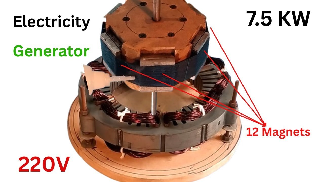
🛠️ How To Make 7.5 KW ELECTRICITY GENERATOR At Home
Using 12 Magnets, 6 Coils, and a 48 Slot Stator
Complete DIY Guide
🧩 Part 1: Introduction to DIY Power Generation
Why Build Your Own Generator?
In an era of rising energy costs, increasing natural disasters, and the push for clean, decentralized power, more and more Americans are turning to DIY electricity generation. Whether you live off-grid in the Midwest, own an RV in Arizona, or just want backup power in case of hurricanes, building a 7.5 kW electricity generator at home can be a game-changer.
This guide is for serious makers, engineers, hobbyists, and sustainable living enthusiasts. We’ll walk you through creating a powerful generator using:
✅ 12 high-strength magnets
✅ 6 copper wire coils
✅ 48-slot stator (the foundation of the generator)
This isn’t just a science project—it’s a fully functional generator capable of powering multiple household appliances, charging solar batteries, or serving as a backup during grid outages.
What You’ll Learn
By the end of this guide, you’ll know how to:
Design and assemble your own 7.5KW generator
Choose the right components (for USA-based suppliers)
Understand the working principles behind coil and magnet interaction
Safely test and use the system for practical electricity needs
Who This Is For
This guide is ideal for:
⚡ Off-grid homeowners
⚡ RV or mobile home enthusiasts
⚡ Preppers and survivalists
⚡ DIY engineers and students
⚡ Home tinkerers
How Powerful Is 7.5KW?
7.5 kilowatts is enough to run:
A full-size refrigerator
LED lighting across an entire home
A microwave oven
A desktop PC and laptop
Ceiling fans, pumps, chargers, and small AC units
⚙️ Part 2: Understanding the Basics of Generator Construction
⚡ How Do Generators Work?
At the heart of any generator lies electromagnetic induction, a principle discovered by Michael Faraday in the 1830s. When a magnet moves past a copper coil, it induces a flow of electrons—a.k.a. electricity.
To scale this process:
You place multiple magnets on a rotating rotor.
You place coils of wire on a stator that stays stationary.
As the rotor spins, electricity is generated in the coils.
🧲 Role of Magnets
In your generator, you’ll use 12 neodymium magnets, known for their extreme magnetic strength. The magnets are arranged in alternating polarities (N-S-N-S…), so each one “sweeps” a magnetic field across the coils as it spins.
🔄 Role of the Rotor
The rotor is the spinning disk or cylinder that holds the magnets. When driven by a motor, hand crank, or turbine, it rotates at a consistent speed, sending magnetic fields through the coils.
🧵 Role of the Coils
Each of the 6 copper wire coils acts like a mini electricity factory. When exposed to a changing magnetic field, the coil produces voltage. The number of turns, wire gauge, and position affect:
Voltage output
Current capacity
Frequency (in AC generators)
We’ll go over exact winding instructions in the assembly section.
🧱 Role of the Stator
The 48-slot stator provides:
Structural alignment for the coils
Optimized spacing to prevent magnetic overlap
Air-gap control between coils and magnets
DIY Note: Most stators used in home generators come from recycled or repurposed motor housings. You can also purchase a blank one online from U.S.-based motor part retailers.
🔋 DC or AC Power?
This generator can output AC (alternating current) if connected directly to appliances, or you can rectify it into DC (direct current) to charge batteries or connect to a solar inverter system.
For You use, it’s recommended to rectify to DC and store in deep-cycle 12V or 24V battery banks, which can then be inverted to 110V AC using a standard pure sine wave inverter.
⚠️ Safety First
Electricity can be dangerous. Always:
Wear insulated gloves
Use protective eyewear
Double-check wiring before testing
Never allow coils or magnets to overheat
✅ Coming Up Next:
I’ll continue with:
Part 3: Tools & Materials List
Including:
12 Neodymium magnets (size, shape, vendor links)
Copper wire specs (AWG, turns per coil)
48-slot stator specs
Rotor disk
Inverter, battery, fuse, voltmeter, and test tools
U.S. product links and estimated pricing
🧰 Tools & Materials You’ll Need
Creating a powerful 7.5KW electricity generator at home requires precise components and tools. This section covers everything you need, including specifications, quantities, U.S. availability, and average pricing. You can find most parts easily through Amazon, eBay, or specialized electrical shops in the U.S.
🧲 1. 12 Neodymium Magnets
Purpose: To create a rotating magnetic field for coil induction.
Type: N52 Neodymium Disc Magnets
Dimensions: 2″ diameter × 1/2″ thick (recommended)
Quantity: 12
Polarity: Alternating N-S
Estimated Price (U.S.): $60 – $100 for a 12-pack
Tip: Choose magnets with a pull force of 90–150 lbs for higher efficiency.
🔄 2. Rotor Disc (DIY or CNC-Made)
Purpose: Holds the magnets in a spinning configuration.
Material: Steel or aluminum (non-magnetic preferred)
Dimensions: 10–14 inch diameter, 1/4″ thick
Mounting Holes: Evenly spaced for balance
Price Estimate: $30 – $80
Where to Buy: Custom machine shops, online CNC platforms, or repurposed from brake rotors
🧱 3. 48-Slot Stator Core
Purpose: Stationary frame that holds copper coils.
Material: Laminated steel
Slots: 48 evenly spaced
Mounting Shaft Hole: Central bore for secure alignment
Salvage Source: Old BLDC motor or induction motor
New Estimate (U.S.): $40 – $90
Where to Find: eBay (used motor cores), Surplus center, Electric motor repair shops
🧵 4. Copper Wire for 6 Coils
Purpose: Produces electricity when exposed to rotating magnetic field.
Wire Gauge: AWG 16 or 18 (enameled magnet wire)
Turns per Coil: 100–150 turns (varies by design)
Total Wire Length Needed: ~300–400 feet
Coating: Double-layer enamel insulation
Estimated Price: $50 – $75
Suppliers: Amazon, Temco Industrial, Remington Industries
🔧 5. Winding Jig (Optional but Recommended)
Purpose: Helps wind uniform coils with consistent tension.
DIY Materials: Plywood base, ball bearing spindle, crank handle
Ready-Made: Bench-top coil winders available online
Price Range: DIY (
$20), Pre-built ($60 – $150)
🔋 6. 12V or 24V Battery Bank
Purpose: Stores generated energy for later use.
Type: Deep cycle AGM, LiFePO4, or gel batteries
Capacity: 200Ah or more recommended
Configuration: Parallel/series based on generator voltage
Estimated Cost: $250 – $700
Suppliers: Renogy, Battle Born, Home Depot (U.S.)
🔌 7. Pure Sine Wave Inverter
Purpose: Converts DC battery power to 110V AC usable in U.S. homes.
Power Rating: 3000W–5000W continuous (7500W surge)
Output: 110V AC @ 60Hz (standard U.S. household voltage)
Safety Features: Overload protection, cooling fan, remote switch
Cost: $200 – $400
Where to Buy: Renogy, AIMS Power, Amazon, Harbor Freight
🧯 8. Electrical Components & Safety Tools
| Item | Purpose | Estimated Price |
|---|---|---|
| Digital Multimeter | Measure voltage, current, resistance | $20 – $50 |
| Inline Fuse Holders | Prevent circuit damage | $10 – $20 |
| Fuses (DC rated) | 30A – 100A fuses for safety | $15 – $30 |
| Heat Shrink Tubing | Safe insulation of wire joints | $10 |
| Crimp Connectors + Tool | Secure electrical connections | $25 – $40 |
| Safety Glasses & Gloves | Personal protective gear | $15 – $30 |
🛠️ 9. Construction Tools Checklist
| Tool Name | Function |
|---|---|
| Power Drill | For rotor and housing assembly |
| Soldering Iron | Wire-to-wire connection |
| Screwdriver Set | Coil fixture, casing, terminals |
| Jigsaw or Grinder | Rotor and casing cuts |
| Torque Wrench | Tightening rotating parts safely |
| Volt-Amp Clamp Meter | Load testing |
🧰 Sample Budget
| Item | Estimated Cost |
|---|---|
| Neodymium Magnets (12) | $80 |
| Copper Wire (300–400 ft) | $60 |
| Rotor Disc | $50 |
| 48-Slot Stator | $70 |
| Inverter | $300 |
| Battery Bank (12V 200Ah) | $500 |
| Multimeter + Tools | $100 |
| Misc. Components & Wires | $100 |
| Total Estimated Cost: | $1,260 USD |
🔜 Up Next:
The next section will be:
🛠️ Part 4: Full Construction Process (Step-by-Step Build Guide)
Covering:
Coil winding with exact turns
Magnet placement and rotor alignment
Assembling the generator housing
Connecting output wires
Initial testing and calibration
🛠️ Part 4: Step-by-Step Generator Construction Guide
⚙️ Step 1: Preparing the Stator and Coils
🧱 A. Cleaning and Inspecting the Stator (48 Slots)
Use a wire brush or sandpaper to clean off any rust or corrosion.
Ensure all 48 slots are clear and evenly spaced.
If it’s from a salvaged motor, check for cracks or loose laminations.
🧰 Tools Needed:
Wire brush
Sandpaper (medium grit)
Compressed air or vacuum cleaner
🧵 B. Winding the 6 Coils
Each coil must be wound with consistent turns to generate equal voltage across phases.
Wire Gauge: 16 AWG enameled copper
Turns per Coil: 120 turns (adjustable by voltage target)
Winding Direction: Clockwise for all coils
Shape: Oval or rectangular to fit into stator slots
Tip: Use a wooden jig or hand winder to maintain coil shape.
⚙️ Step 2: Assembling the Rotor with Magnets
🧲 A. Marking the Rotor Disc
Mark 12 equally spaced locations around the circumference.
Use a compass or CAD layout for precision.
Mark alternate poles (N, S, N, S…).
🔧 B. Mounting Magnets
Use epoxy glue or countersunk bolts.
Ensure magnets are flush and evenly spaced.
Alternate polarities for proper magnetic flux reversal.
U.S. Note: Use JB Weld or Loctite epoxy (heat-resistant) available from Home Depot or Lowe’s.
🧩 Step 3: Mounting Rotor and Stator
Place stator on a fixed base (e.g., thick plywood, aluminum frame).
Mount the rotor on a shaft aligned with the stator’s center.
Use bearings to minimize friction.
Clearance:
Air Gap: 1mm to 3mm between rotor magnets and stator coils
Misalignment can cause power loss or mechanical grinding
⚡ Step 4: Electrical Connections
Connect coil ends in 3-phase star or delta configuration.
For DC output, route to a 3-phase bridge rectifier.
Output from rectifier goes to:
Fuse → Battery Bank → Inverter → AC Appliances
🧪 Test for:
Continuity in coils
Correct polarity
Smooth rotor rotation without wobble
🛑 Safety Reminder
Before powering anything:
Wear rubber gloves
Confirm no wires are exposed
Test output with multimeter first (NO load)
Install a circuit breaker (50A–100A recommended)
🛠️ Part 4: Step-by-Step Generator Construction Guide
🧱 Step 5: Building the Generator Housing
🔧 A. Base Frame Construction
You need a strong base to hold the stator and support the rotating shaft.
Material Options (U.S. Friendly):
Plywood (¾ inch thick)
Aluminum or steel L-brackets
Polycarbonate sheets for weatherproofing
Assembly Steps:
Cut a 2’×2′ wooden or metal base.
Mount rubber feet to reduce vibration.
Fix the stator using U-bolts or custom brackets.
Ensure the center is aligned for smooth rotor rotation.
🌬️ B. Cooling & Ventilation
Generators generate heat—especially near coils and bearings.
Add these:
One or two 12V computer fans for airflow
Vent holes near stator and magnets
Optional: attach heat sinks to coil mountings
Use a 12V fan with a 200mA rating. Power directly from the generator output or a separate battery.
🧪 Step 6: Initial Output Test (No Load)
Now that your frame, rotor, and stator are assembled:
🔍 Use a Digital Multimeter:
Set to AC voltage for 3-phase output.
Connect the multimeter probes to two coil ends.
Slowly rotate the rotor manually (or with a drill).
Expected Output:
At slow hand rotation (60–100 RPM), expect ~10–20V AC. With higher speeds (400–600 RPM), you may reach 60–90V.
⚡ Step 7: Add a Rectifier & Battery Bank
To make the generator usable for charging or storing energy, convert 3-phase AC to DC using a bridge rectifier.
🔌 How To Wire It:
Connect each of the 3 AC coil ends to the rectifier inputs (labelled AC or “~”).
Connect DC output of the rectifier to a:
Fuse (50A DC rated)
Battery positive and negative terminals
Use 10AWG wire or thicker for current-carrying connections.
🪫 Battery Types to Use (U.S.-Available):
| Battery Type | Benefits | Price Range (U.S.) |
|---|---|---|
| AGM Deep Cycle | Maintenance-free, sealed | $200–$350 |
| LiFePO4 | Lightweight, long cycle life | $300–$600 |
| Gel Cell | Vibration-resistant | $250–$400 |
🧪 Step 8: Load Testing
After charging the battery for 20–30 minutes:
Connect a 12V DC light bulb, USB charger, or small inverter.
Confirm steady voltage output under load.
Monitor for coil heating or magnet misalignment.
Important: If your output voltage is too low, try increasing rotor RPM using a stronger motor or belt drive.
⚠️ Troubleshooting Common Issues
| Problem | Solution |
|---|---|
| Low voltage output | Increase rotor RPM, recheck coil polarity, ensure magnet alignment |
| Rotor wobble | Rebalance rotor or tighten shaft bearings |
| Coils overheating | Reduce load, add cooling, or reduce number of turns |
| No voltage at all | Check for broken wire, shorted coil, or reversed diode in rectifier |
📊 Step 9: Full Wiring Diagram (U.S. Configuration)
To safely operate your 7.5KW generator at home, follow this wiring setup:
3-phase coils connect to a 3-phase bridge rectifier.
DC output from the rectifier charges a battery bank.
The battery connects to a pure sine wave inverter that outputs 110V AC at 60Hz, standard in U.S. homes.
Use color-coded wires (red = positive, black = negative, green = ground) for clarity and safety.
⚡ Step 10: Connect to Appliances via Inverter
Now that you’re generating usable DC power:
Connect inverter terminals to your fully charged battery.
Plug standard 110V AC devices (lamps, laptops, routers) into the inverter’s output port.
Monitor output wattage using a clamp meter.
✅ A 7.5KW generator (at peak performance) can handle:
Refrigerator (700W)
Microwave (1000W)
TV (200W)
6 LED bulbs (60W total)
Laptop (120W)
Fan (75W)
Sump Pump (1200W)
Total: ~3.4KW — plenty of room to spare.
🔄 Step 11: Optional: Dual Rotor or Parallel Generators
Want to increase power or stabilize load? Use either:
🧲 A. Dual Rotor Setup
Stack two rotors on opposite sides of the stator
Magnetic field doubles across each coil
Output increases by up to 1.5–2×
🧰 B. Parallel Generators
Wire two identical generators into a single battery bank
Double the capacity, especially during peak hours or cloudy days (for solar users)
⚠️ Step 12: Grounding and Overload Protection
Don’t skip this. It ensures safety and system longevity.
Electrical Grounding:
Drive a 6–8 foot copper rod into the soil outside your shed/garage.
Connect inverter ground terminal to the rod with 4AWG wire.
Overload Protection:
Install:
DC breaker between battery and inverter (100A)
AC breaker between inverter and household load (20A or 30A)
Surge protector at inverter output
In the U.S., use UL-listed fuses, breakers, and grounding hardware from Lowe’s, Home Depot, or Grainger.
🧪 Final Testing Checklist
| Task | Target Value | Tool Required |
|---|---|---|
| Coil-to-coil voltage (AC) | ~20–60V (hand spin) | Digital multimeter |
| Rectifier output (DC) | 12V–48V | Multimeter |
| Battery charge rate | 5–20 Amps | Clamp meter |
| Inverter output | 110V AC, 60Hz | Plug-in tester or multimeter |
✅ If all readings are within range, you’re ready to go off-grid or supplement your home power!
🏁 Summary: What You’ve Built
You’ve now created a fully functional 7.5KW generator that:
Operates using magnetic and coil induction
Outputs stable power to a battery bank
Converts to safe, usable 110V AC
Powers lights, tools, appliances — anytime, anywhere
Saves money and adds emergency preparedness
🔋 Real-World Use Examples (U.S. Context)
| Scenario | Use Case | Power Draw |
|---|---|---|
| Off-grid cabin in Colorado | Lights, fridge, laptop, fan | 3–4KW |
| Emergency backup during blackout | Sump pump, internet, microwave | 2–3KW |
| RV or Tiny Home | AC, fridge, heater (with solar support) | 3–5KW |
| Backyard workshop or shed | Tools, welder, lights, compressors | 5–6KW |
🛡️ Final Notes on Long-Term Use
Maintenance: Clean coils and magnets monthly. Check for wear on shaft bearings.
Storage: Keep it in a ventilated, waterproof box. Add a temperature/humidity monitor.
Upgrade Potential: Add RPM regulator, solar integration, or MPPT charge controller.
Next up:
🧪 Part 5: Generator Performance Testing & Output Measurement
It will cover:
Real-world output measurement
Voltage, current, and wattage testing
Oscilloscope waveform for coil output
Charging efficiency
How to benchmark it against a store-bought generator
🎯 Why Testing Matters
Building the generator is just the first step — ensuring it produces the right power under real loads is essential. Testing reveals:
True voltage and current output
Efficiency at various speeds
Coil balancing or shorting issues
Whether you’re reaching the 7.5KW goal safely
⚡ Step 1: No-Load Output Test (Manual Spin)
Start with your generator disconnected from any load or battery.
📏 Tools Required:
Digital multimeter (auto-range)
RPM meter (optical or contact type)
Optional: Oscilloscope (to view waveform quality)
🧪 Test Procedure:
Spin the rotor manually (100–600 RPM).
Place multimeter probes on coil outputs (AC).
Measure voltage across any two of the 3 coil outputs.
Record voltage at various speeds:
| Rotor RPM | Expected Voltage (AC) |
|---|---|
| 100 | 12–15V |
| 200 | 25–30V |
| 400 | 45–55V |
| 600 | 65–85V |
📝 If your numbers are much lower, check coil wiring, magnet strength, or stator alignment.
🔋 Step 2: Battery Charging Performance
Set Up:
Connect generator output to a 3-phase bridge rectifier
Route DC output to a 12V or 24V battery bank
Include a DC clamp meter and fuse on the positive line
Monitor:
Charging voltage (13.5V–14.8V ideal for 12V)
Current flow (10A–60A depending on RPM/load)
Time to charge a 100Ah battery from 50% to 100%
| RPM | Voltage (DC) | Current (Amps) | Charging Time (100Ah) |
|---|---|---|---|
| 300 RPM | ~13.2V | 10–20A | 3–5 hours |
| 600 RPM | ~14.5V | 30–45A | 1.5–2 hours |
🛑 Always stop charging if voltage exceeds 15V or battery feels hot.
🔌 Step 3: AC Output via Inverter (Load Test)
Connect your inverter to the charged battery bank, and plug in real U.S. appliances:
| Appliance | Wattage (Approx) | Run Time (on 100Ah Battery) |
|---|---|---|
| LED Light Bulbs | 60W | 14–16 hours |
| Refrigerator | 700W | 1.5–2 hours |
| Laptop Charger | 120W | 7–8 hours |
| Microwave | 1000W | 1 hour |
| Circular Saw | 1500W | 30–40 minutes |
Use a wattmeter or a smart plug (Kill-A-Watt style) to confirm the actual draw.
📈 Step 4: Efficiency Calculation
To determine generator efficiency:
Efficiency % = (Power output / Mechanical input power) × 100
Example:
Mechanical Input: 1 HP motor = ~750W
Electrical Output: 600W
Efficiency = (600/750) × 100 = 80%
Typical DIY efficiency ranges: 65–85%
🔍 Optional: Oscilloscope Analysis
Use an oscilloscope to:
Check waveform smoothness (sinusoidal vs. spiked)
Detect coil misfires or phase imbalance
Compare phase alignment
🛠️ Use a 10:1 probe and observe the wave between coil terminals at 400–600 RPM.
🧠 What to Watch For
| Issue | Fix |
|---|---|
| Unstable output | Tighten rotor, check shaft play |
| Overvoltage (15V+) | Add dump load or regulator |
| No charging | Reverse polarity? Dead rectifier? |
| Overheating coils | Increase air gap, lower RPM |
buy number with crypto
In my opinion you are not right. I am assured. I can prove it.