
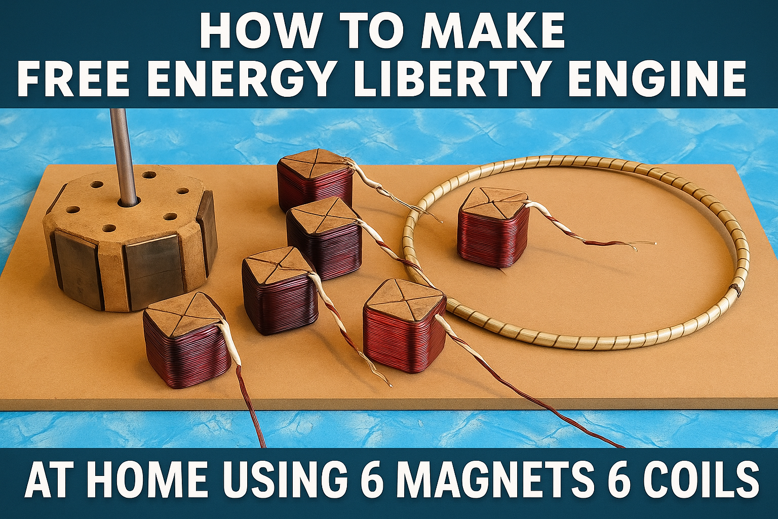
How To Make a FREE ENERGY LIBERTY ENGINE at Home Using 6 Magnets and 6 Coils
Table of Contents
Introduction to Free Energy
Understanding the Liberty Engine Concept
Materials and Tools You’ll Need
Core Principles: Magnetic Induction & Coils
Step-by-Step Liberty Engine Construction Guide
Wiring & Connections
Testing the Output
Safety Measures
Troubleshooting Common Issues
Efficiency Optimization Tips
Realistic Expectations & Limitations
Legal & Ethical Considerations
FAQs
Conclusion
1. Introduction to Free Energy
The idea of free energy liberty engine has fascinated inventors and engineers for decades. While traditional electricity depends on fuel consumption or solar, wind, or water sources, free energy devices aim to use magnetic and inductive properties to create self-sustaining systems. One of the latest DIY trends is the Liberty Engine, a magnet-based motor generator system that’s designed for home experimentation.
While the term “free energy” doesn’t mean breaking the laws of thermodynamics, it refers to systems that reduce or recycle energy loss to increase overall efficiency — especially through permanent magnets and electromagnetic induction.
2. Understanding the Liberty Engine Concept
A Liberty Engine is a type of homemade generator that uses:
Permanent magnets (to provide a constant magnetic field)
Copper coils (to induce current through motion)
A rotor/stator setup (to generate relative motion)
This design relies on the interaction between magnets and coils — where motion between the two induces electrical current in the coil windings (Faraday’s Law).
This DIY project uses:
6 neodymium magnets arranged on a rotor
6 copper wire coils mounted on a stator or base
When set in motion (manually or with an external push), the rotor’s magnets create fluctuating magnetic fields through the stationary coils — thus generating alternating current (AC).
3. Materials and Tools You’ll Need
🔧 Basic Materials:
6 Neodymium magnets (cylindrical or disc-shaped)
6 Copper wire coils (enameled, 24–28 AWG, 500 turns per coil)
1 Rotor disc (acrylic, plastic, or plywood)
1 Stator base (non-metallic, stable material)
1 Steel shaft (for rotation)
2 Ball bearings (for smooth motion)
1 Bridge rectifier (to convert AC to DC)
1 Capacitor or battery (to store output)
Glue gun, screws, nuts, washers
⚙️ Tools:
Drill machine
Soldering iron
Multimeter
Hot glue gun
Wire stripper
Ruler and compass
4. Core Principles: Magnetic Induction & Coils
💡 Faraday’s Law of Electromagnetic Induction:
Whenever a magnetic field moves past a coil (or a coil moves past a magnet), an electric current is induced in the coil. This is the basic principle of electric generators.
🧲 Role of Magnets:
Neodymium magnets are ideal because of their strong field. Their movement over coils produces significant voltage spikes.
🌀 Coil Construction:
Each coil must be uniformly wound and insulated with enamel. 500 turns is ideal for household-level generation. More turns = more voltage but less current.
5. Step-by-Step Liberty Engine Construction Guide
🔨 Step 1: Design Layout
Draw a circle (rotor) and mark 6 equidistant points on the circumference.
The magnets will be placed at these positions with alternating polarity: N–S–N–S–N–S
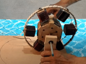
🔨 Step 2: Construct the Rotor
Fix the 6 magnets onto the rotor with glue or epoxy.
Ensure all magnets are securely attached and the polarity alternates.
Drill a center hole in the rotor for the shaft.
🔨 Step 3: Build the Stator Base
Mount 6 coils on a stable surface forming a circle aligned with the rotor.
Leave about 2–3mm gap between coils and magnets.
Secure the coils using hot glue.
🔨 Step 4: Install Bearings & Shaft
Insert the steel shaft through the rotor.
Place ball bearings at both ends to ensure smooth, low-friction rotation.
Mount the rotor on a stand (wood or plastic frame).
6. Wiring & Connections
🧷 Coil Wiring:
Wire the 6 coils in series or parallel, depending on the desired voltage/current.
Series = Higher voltage, lower current
Parallel = Higher current, lower voltage
🔌 Add Rectifier and Capacitor:
Connect the coil outputs to a bridge rectifier.
The rectifier outputs DC.
Connect a capacitor or 12V battery to store energy.
📏 Testing Voltage:
Use a multimeter to measure AC at coil output and DC after the rectifier. A well-balanced setup can produce 5V to 20V with minimal RPM.
EXPERIMENT
7. Testing the Output
✅ Test 1: Manual Spin
Spin the rotor manually and check coil output.
Multimeter should detect alternating current across each coil.
✅ Test 2: Drill Motor Spin
Use a drill machine to spin the rotor at a constant RPM.
Measure voltage before and after the rectifier.
✅ Test 3: Lighting a Load
Try powering an LED or small fan.
If successful, your Liberty Engine is working!
8. Safety Measures
While building and testing:
Keep magnets away from electronics and credit cards.
Use insulated gloves when handling wires.
Don’t short the capacitor — it can explode.
Avoid spinning the rotor too fast — can damage coils.
9. Troubleshooting Common Issues
| Problem | Possible Cause | Solution |
|---|---|---|
| No voltage output | Magnet polarity is not alternating | Rearrange magnets |
| Low voltage | Coil turns too low | Increase turns to 500–1000 |
| Rotor not spinning freely | Shaft or bearing misalignment | Re-check mounting and balance |
| Heat in rectifier or capacitor | Overload or short circuit | Add current-limiting resistor |
| Output drops after few seconds | Poor coil soldering or loose joints | Inspect and fix all electrical contacts |
10. Efficiency Optimization Tips
Increase coil turns to raise voltage output.
Use magnetic shielding to prevent field leakage.
Balance rotor weight to avoid wobbling.
Use graphite lubricant on bearings for smoother motion.
Align magnets and coils precisely to reduce flux losses.
Optional:
Add a mechanical crank or DC motor to automate rotation.
Use MPPT charge controller if connecting to a battery.
11. Realistic Expectations & Limitations
While this project is great for learning and experimentation, it’s important to understand:
You won’t power your whole house.
It can power LEDs, small fans, mobile chargers, etc.
Continuous rotation requires manual or external energy.
It’s not perpetual motion — it’s a high-efficiency generator using kinetic energy input.
12. Legal & Ethical Considerations
Before connecting the Liberty Engine to a home circuit:
Do NOT connect it directly to mains.
Avoid misleading claims about “infinite energy.”
This device is for educational and experimental use only.
Respect local energy regulations and safety standards.
13. FAQs
❓ Can this Liberty Engine run by itself?
No. You need to spin the rotor manually or via motor. It’s not a perpetual motion machine.
❓ How much energy can I store?
Depends on coil quality, speed of rotation, and rectifier-capacitor setup. Usually enough for low-wattage devices.
❓ Can I increase magnet or coil count?
Yes! You can scale up to 12 magnets and 12 coils for higher output, but it requires better alignment and stronger support.
❓ How long will the magnets last?
Neodymium magnets can last 10–20 years without losing strength unless exposed to high heat.
14. Conclusion
Creating a Free Energy Liberty Engine using 6 magnets and 6 coils is not only a rewarding DIY project but also a hands-on educational tool for understanding the science of energy generation.
While it’s not a replacement for conventional power systems, it’s a great way to explore:
Magnetism
Electromagnetic induction
Alternative energy experimentation
By following the steps above carefully, you’ll build a working prototype capable of producing real electricity — proving that with the right components, even a beginner can create power from motion.
Your blog is a true gem in the world of online content. I’m continually impressed by the depth of your research and the clarity of your writing. Thank you for sharing your wisdom with us.
The matchless theme, is pleasant to me 🙂